**这是本文档旧的修订版!**
Delta调制(DM)
Delta调试是一种将编码信息信号转换成1个二进制位流的调制方法,在这里只需要1位将1个电平进行编码,这种方式可以每一个取样点传输1位。
由于PCM具有将消息信号直接转换成二进制编码脉冲序列的特性,因此增加了系统的带宽要求。因此,为了消除PCM的缺点,采用了增量调制。
Delta调制的工作原理
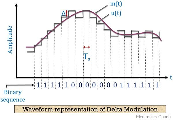
DM的工作原理是将当前采样值与之前采样值进行比较,两者的差值决定传输值的增量或减量。简单地说,当两个样本值比较时,我们得到的差异要么具有正极性,要么具有负极性。 如果极性差为正,则Δ表示的信号步长增加1。而当极性差为负时,则信号的阶跃减小,即Δ的减小。当+Δ被注意到,即步长增加时,则传输1。而对于-Δ,即步长减小,则传递0。因此,每个样本只允许传输一个二进制位。
Block diagram for Delta Modulation
Let us first understand the generation of delta modulated signal.
Generation of delta modulated signal
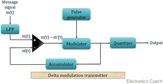
The block diagram for the generation delta modulated signal is shown below:
As we can see the above figure consists of an LPF, a comparator, a product modulator along with pulse generator and quantizer. Here, a feedback path is also provided to the circuit, where the output of modulator acts as input to the comparator.
The message signal that is to be transmitted is fed to a low pass filter that passes the low-frequency component and eliminates the high-frequency component. It is also referred to as aliasing filter.
The output of LPF is then given to a comparator unit, which compares the message signal m(t) with an arbitrary signal m'(t) for the first time. The comparator after comparing 2 signals generates the difference between the two.
The difference can be of either positive polarity or negative polarity. This depends on message and arbitrary signals that are getting subtracted.
This difference signal now acts as input to the product modulator. Another input to the modulator is a pulse signal generated by the pulse generator. These two signals are multiplied in the modulator.
The output of the modulator is a pulsed signal whose pulses will be of equal magnitude having polarity either positive and negative.
The polarity totally depends on the output of the comparator. The output of the modulator is given to quantizer. The quantizer generates the output in the form of steps.
If positive magnitude pulse is provided to the quantizer as its input then quantizer performs increment by 1 step size, Δ. It is very easy to understand that positive pulse at the output of the modulator shows that message signal is greater than the arbitrary signal. Thus quantizer increases Δ by 1.
Similarly, in the case of negative magnitude pulse, the step size gets decreased by 1. This is so because m'(t) exceeds m(t), thereby generating a pulse of negative polarity. Thus, quantizer decreases Δ by 1.
The output of the modulator at the same time, through a feedback path, is provided to the accumulator.
An accumulator is nothing but a device that stores the signal for further operation. The output of the accumulator now behaves like the second input of the comparator. Thus, we say that the present sample value is compared with the previous one for further operation.
Hence the process repeats in such a manner.
In the end, depending on the staircase signal if the step size is +Δ then binary 1 is transmitted and if it is –Δ then binary 0 is transmitted.
Waveform Representation of Delta Modulation
The figure below shows the delta modulation waveform:
 Here, the analog input signal is m(t) and the quantized signal is denoted by u(t). The binary sequence according to the step size that is actually transmitted is shown at the bottom of the figure shown above.
Detection of delta modulated signal
The detection of a delta modulated signal is not a complex process and is somewhat reverse of generation of a delta modulated signal.
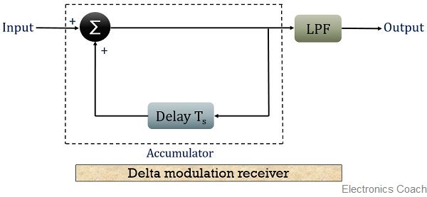
The figure below shows the block diagram for the representation of detection of delta modulated signal.
 The detection circuitry basically consists of an accumulator and an LPF. The binary signal transmitted is provided to the accumulator section.
The accumulator consists of a summation unit and a delay unit. The transmitted signal along with the delayed signal is added at the summation unit.
If here the input is binary 1 then after a delay the output of the accumulator shown increased step size +Δ. However, in the case of binary 0 as input, a decrease in step size is noticed. This generates the staircase signal equivalent to the message signal.
The output of the accumulator is provided to the LPF that smoothens the staircase signal in order to regenerate the original message signal.
Advantages of delta modulation
- Due to transmission of 1 bit per sample, it permits low channel bandwidth as well as signaling rate.
- ADC is not required. Thus permits easy generation and detection.
Disadvantages of delta modulation
- Delta modulation leads to drawbacks such as slope overload distortion and granular noise.
Applications of delta modulation It is widely used in radio communication devices and digital voice storage and voice information transmission where signal quality is less important.
