**这是本文档旧的修订版!**
Delta调制(DM)
Definition: A modulation technique that converts or encodes message signal into a binary bit stream is known as Delta Modulation. Here only 1 bit is used to encode 1 voltage level thus, the technique allows transmission of only 1 bit per sample.
As PCM has the property of converting message signal directly into a sequence of a binary coded pulse, this resultantly increases the bandwidth requirement of the system. So, in order to remove the drawbacks of PCM, delta modulation is used.
Delta Modulation (DM)
Definition: A modulation technique that converts or encodes message signal into a binary bit stream is known as Delta Modulation. Here only 1 bit is used to encode 1 voltage level thus, the technique allows transmission of only 1 bit per sample.
As PCM has the property of converting message signal directly into a sequence of a binary coded pulse, this resultantly increases the bandwidth requirement of the system. So, in order to remove the drawbacks of PCM, delta modulation is used.
Operating principle of Delta Modulation
The operating principle of DM is such that, a comparison between present and previously sampled value is performed, the difference of which decides the increment or decrement in the transmitted values.
Simply put, when the two sample values are compared, either we get difference having a positive polarity or negative polarity.
If the difference polarity is positive, then the step of the signal denoted by Δ is increased by 1. As against in case when difference polarity is negative then step of the signal is decreased i.e., reduction in Δ.
When +Δ is noticed i.e., increase in step size, then 1 is transmitted. However, in the case of –Δ i.e., decrease in step size, 0 is transmitted.
Hence, allowing only a single binary bit to get transmitted for each sample.
Block diagram for Delta Modulation
Let us first understand the generation of delta modulated signal.
Generation of delta modulated signal
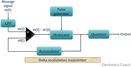
The block diagram for the generation delta modulated signal is shown below:
As we can see the above figure consists of an LPF, a comparator, a product modulator along with pulse generator and quantizer. Here, a feedback path is also provided to the circuit, where the output of modulator acts as input to the comparator.
The message signal that is to be transmitted is fed to a low pass filter that passes the low-frequency component and eliminates the high-frequency component. It is also referred to as aliasing filter.
The output of LPF is then given to a comparator unit, which compares the message signal m(t) with an arbitrary signal m'(t) for the first time. The comparator after comparing 2 signals generates the difference between the two.
