尽管与其他PCB设计软件具有相似性,但KiCad的特点是独特的工作流程,其中原理图元件和封装是分开的。 仅在创建原理图之后才会为元器件分配封装。
2.1. 概述
像其它的CAD工具软件一样,KiCad工作流程包括两个重要的任务:原理图绘制和电路板的布局布线,为实现这两个任务就需要原理图源器件符号库和PCB封装库的构建。 KiCad工具自身包含了很多元器件的原理图符号库和封装库,并且还具有创建新元器件符号库和封装库的工具。
- KiCad: 项目管理
- Eeschema: 原理图编辑器和元器件编辑器
- Pcbnew: 电路板布局布线编辑以及封装库编辑器
- GerbView: Gerber查看
还包含了3种实用工具:
- Bitmap2Component: 可以制作图标的元器件制作工具,它能够从一个Bitmap图像来创建原理图元器件或封装库。
- PcbCalculator: 很有用的一个计算器,用来计算稳压器、线宽和电流的关系、传输线等。
- Pl Editor: 页面布局编辑器。
这些工具一般是通过项目管理页面启动运行,也可以作为单独的工具进行运行。
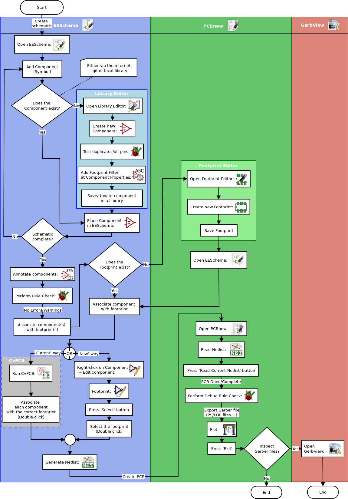
下图就是一个KiCad工作流程图,它标明了您需要采取的步骤以及相应的顺序。 适用时,会添加图标以方便使用。

KiCad流程图
有关创建组件的更多信息,请阅读“制作原理图组件”这部分内容。想了解如何创建新封装库,请参阅“制作元器件封装”。
Quicklib是一个能够基于Web的界面快速创建KiCad元器件符号库的工具,你可以参阅“使用Quicklib制作原理图符号库”来获取相关的使用信息。
2.2. 前向注释和后向注释
完成电子原理图设计后,下一步就是将其传输到PCB。通常,可能需要添加其它元器件、元器件的封装调整为不同的大小、网络重命名等。这可以通过两种方式来完成:前向注释或后向注释。
正向注释是将原理图信息发送到相应PCB布局的过程。这是一个基本功能,因为您必须至少执行一次才能将原理图导入PCB。在此以后,正向注释允许向PCB发送增量的原理图更改。有关前向注释的详细信息,请参阅“前向注释”一节。
后向注释是将PCB布局更改的信息发回到相应的原理图的过程。最常见的两种后向注释就是进行“门交换”和“引脚交换”。在这些情况下,有功能相同的“门”或“引脚”,但只有在布局期间才能够根据布线的便利来最终确定“门”或“引脚”的最佳安排。一旦在PCB中做出选择,则将此更改传递给原理图。
3. 使用KiCad
3.1. 快捷键
KiCad有两种相关但不同的快捷键:加速键和热键。 两者都用于通过使用键盘而不是鼠标来更改命令来加速KiCad的工作。
3.1.1. 加速键
3.1.2. 热键
热键等于加速键和鼠标左键的组合功能。 使用热键可以立即在当前光标位置启动命令。 使用热键快速更改命令,而不会中断工作流程。
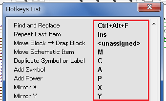
要查看任何KiCad工具中的热键,请转到“帮助→列出热键”或按Ctrl + F1:

热键
您可以从“首选项→热键选项”菜单中编辑热键的分配,然后导入或导出它们。
注意:在本文档中,热键用括号表示,如下所示:[a]。 如果看到[a],只需在键盘上键入“a”键即可。
3.1.3. 举例
考虑在原理图中添加导线的简单示例。
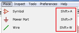
要使用加速键,请按“Shift + W”调用“添加线”命令(注意光标将改变)。 接下来,左键单击所需的连线的起始位置以开始绘制连线。
使用热键,只需按[w],连线将立即从当前光标位置开始。
安装和配置工作环境
显示配置
Hardware accelerated renderer in Pcbnew and Gerbview requires video card with support of OpenGL v2.1 or higher.
Initialization of the default configuration
The default configuration file named kicad.pro is supplied in kicad/template. It serves as a template for any new project and is used to set the list of library files loaded by Eeschema. A few other parameters for Pcbnew (default text size, default line thickness, etc.) are also stored here. Another default configuration file named fp-lib-table may exist. It will be used only once to create a footprint library list; otherwise the list will be created from scratch.
2.3. Modifying the default configuration
The default kicad.pro file can be freely modified, if desired. Verify that you have write access to kicad/template/kicad.pro Run KiCad and load kicad.pro project. Run Eeschema via KiCad manager. Modify and update the Eeschema configuration, to set the list of libraries you want to use each time you create new projects. Run Pcbnew via KiCad manager. Modify and update the Pcbnew configuration, especially the footprint library list. Pcbnew will create or update a library list file called footprint library table. There are 2 library list files (named fp-lib-table): The first (located in the user home directory) is global for all projects and the second (located in the project directory) is optional and specific to the project.
2.4. Paths configuration
In KiCad, one can define paths using an environment variable. A few environment variables are internally defined by KiCad, and can be used to define paths for libraries, 3D shapes, etc. This is useful when absolute paths are not known or are subject to change (e.g. when you transfer a project to a different computer), and also when one base path is shared by many similar items. Consider the following which may be installed in varying locations: Eeschema component libraries Pcbnew footprint libraries 3D shape files used in footprint definitions For instance, the path to the connect.pretty footprint library, when using the KISYSMOD environment variable, would be defined as ${KISYSMOD}/connect.pretty This option allows you to define a path using an environment variable, and add your own environment variables to define personal paths, if needed. KiCad environment variables: KICADPTEMPLATES Templates used during project creation. If you are using this variable, it must be defined. KICADSYMBOLDIR Base path of symbol library files. KIGITHUB Frequently used in example footprint lib tables. If you are using this variable, it must be defined. KISYS3DMOD Base path of 3D shapes files, and must be defined because an absolute path is not usually used. KISYSMOD Base path of footprint library folders, and must be defined if an absolute path is not used in footprint library names. images/configurepath_dlg.png Note also the environment variable KIPRJMOD is always internally defined by KiCad, and is the current project absolute path. For instance, ${KIPRJMOD}/connect.pretty is always the connect.pretty folder (the pretty footprint library) found inside the current project folder. If you modify the configuration of paths, please quit and restart KiCad to avoid any issues in path handling.
2.5. Initialization of external utilities
You may define your favorite text editor and PDF viewer. These settings are used whenever you want to open a text or PDF file. These settings are accessible from the Preference menu: images/preferences_menu.png
2.5.1. Selection of text editor
Before using a text editor to browse/edit files in the current project, you must choose the text editor you want to use. Select Preferences → Set Text Editor to set the text editor you want to use.
2.5.2. Selection of PDF viewer
You may use the default PDF viewer or choose your own. To change from the default PDF viewer use Preferences → PDF Viewer → Set PDF Viewer to choose the PDF viewer program, then select Preferences → PDF Viewer → Favourite PDF Viewer. On Linux the default PDF viewer is known to be fragile, so selecting your own PDF viewer is recommended.
2.6. Creating a new project
In order to manage a KiCad project consisting of schematic files, printed circuit board files, supplementary libraries, manufacturing files for photo-tracing, drilling and automatic component placement files, it is recommended to create a project as follows: Create a working directory for the project (using KiCad or by other means). In this directory, use KiCad to create a project file (file with extension .pro) via the “Create a new project” or “Create a new project from template” icon. Warning Use a unique directory for each KiCad project. Do not combine multiple projects into a single directory. KiCad creates a file with a .pro extension that maintains a number of parameters for project management (such as the list of libraries used in the schematic). Default names of both main schematic file and printed circuit board file are derived from the name of the project. Thus, if a project called example.pro was created in a directory called example, the default files will be created: example.pro Project management file. example.sch Main schematic file. example.kicad_pcb Printed circuit board file. example.net Netlist file. example.* Various files created by the other utility programs. example-cache.lib Library file automatically created and used by the schematic editor containing a backup of the components used in the schematic.
2.7. Importing a foreign project
KiCad is able to import files created using other software packages. Currently only Eagle 6.x or newer (XML format) is supported. To import a foreign project, you need to select either a schematic or a board file in the import file browser dialog. Imported schematic and board files should have the same base file name (e.g. project.sch and project.brd). Once the requested files are selected, you will be asked to select a directory to store the imported files, which are going to be saved as a KiCad project.
