**这是本文档旧的修订版!**
支持BLE的元器件特性测试仪
硬禾学堂新推出基于CH579(支持BLE的Arm Cortex M0控制器)的元器件测试仪DIY套件,旨在鼓励高校的同学、行业工程师通过嵌入式系统编程深度熟悉元器件的特性,并激发同学们的学习兴趣。

3D效果图
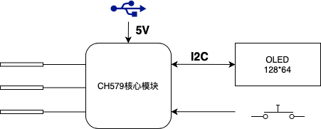
功能框图
功能特性
- 采用CH579做核心控制器:Cortex-M0内核低功耗蓝牙MCU,集成BLE无线通讯的ARM内核32位微控制器。片上集成低功耗蓝牙BLE通讯模块、以太网控制器及收发器、全速USB主机和设备控制器及收发器、段式LCD驱动模块、ADC、触摸按键检测模块、RTC等丰富的外设资源
- 32位ARM Cortex-M0内核,最高40MHz系统主频
- 内置32K SRAM,250KB CodeFlash,2KB DataFlash, 4KB BootLoader,支持ICP、ISP和IAP,支持OTA无线升级
- 支持蓝牙BLE,兼容Bluetooth Low Energy 4.2规范
- 集成2.4GHz RF收发器和基带及链路控制,单端RF接口,无需外部电感,简化板级设计,提供协议栈和应用层API
- 支持3.3V和2.5V电源,范围2.1V~3.6V, 内置DC/DC转换,0dBm发送功率时电流6mA
- 多种低功耗模式:Idle,Halt,Sleep,Shutdown,内置电池电压低压监控,最低电流0.2uA
- 提供10M以太网接口,内置PHY
- 内嵌USB控制器和USB收发器,支持USB2.0全速和低速主机或设备,支持控制/批量/中断同步传输,支持USB type-C主从/电流检测
- 内置实时时钟RTC,支持定时和触发两种模式
- 提供段式LCD驱动接口,支持96点(24×4)LCD面板
- 提供14通道12位ADC模数转换器,支持14通道触摸按键
- 提供4组26位定时器,支持捕捉/采样,支持12路PWM输出
- 提供4组独立UART,兼容16C550,最高通讯波特率可达5Mbps
- 提供2组独立SPI,内置FIFO ,SPI0支持Master和Slave模式,支持DMA
- 提供 LED点阵屏接口:支持1/2/4路数据线
- 支持8位被动并口
- 内置温度传感器
- 提供40个GPIO,32个中断输入
- 内置AES-128加解密单元,芯片唯一ID
- 封装:QFN485×5、QFN284×4,本设计中采用了QFN28封装的器件
- 采用0.96寸、I2C接口的OLED显示
- 一个按键启动测试
设计资料
相关参考
- 挂在钥匙链上的元器件测试仪
- Akshay Baweja基于Arduino Uno制作的元器件测试仪
- AVR-Transistortest - 使用ATmega8, ATmega168, ATmega328或ATmega644以及ATmega1284处理器

- 主要特性:
- 支持ATmega8、ATmega168、ATmega328或ATmega644以及ATmega1284处理器
- 结果可显示在2×16或4×20字符的LCD上.
- 也可显示在控制器为ST7565、NT7108或ST7920的LCD显示屏上. 支持控制器为SSD1306、通过SPI或I2C接口的OLED显示屏
- 一键操作并可以自动关电
- 三个测试端口以增加其通用性
- 自动检测NPN、PNP、N- 或 P-沟MOSFET、JFET、二极管以及小的晶闸管、TRIAC.
- 自动检测管脚的分配,被测的器件可以任意连接到测试端口
- 对于三极管以及达林顿管,可以测量其hFE以及基极到发射极的压降
- 对于三极管和MOSFET可以自动检测以及保护
- Bipolar junction transistors are detected as a transistor with a parasitic transistor (NPNp = NPN + parasitic PNP).
- Up to two resistors will be measured with a resolution down to 0.1 ohm. The measurement range is up to 50 Mohm (Megaohm). Resistors below 10 ohm will be measured with the ESR approach and a resolution of 0.01 ohm if a ATmega168/328 is used. Beware: resolution is not accuracy.
- Capacitors in the range 35pF (picofarad) to 100mF (millifarad) can be measured with a resolution down to 1 pF.
- If the processor has at least 32K flash memory, you can use the samplingADC method from Pieter-Tjerk to get a resolution of up to 0.01 pF for capacitors with lower capacity than 100 pF.
- Resistors and capacitors will be displayed with their respective symbol, pin number and value.
- Up to two diodes will also be displayed with their correctly aligned symbol, pin number and voltage drop.
- If it's a single diode, the parasitic capacitance and reverse current will also be measured.
- For ATmega168/328 a self calibration of zero-capacitance, zero-resistance and other parameters is possible.
- For ATmega168/328 also inductances of 0.01 mH to 20 H can be detected and measured.
- If your processor has at least 32K flash, you can use the samplingADC method to measure lesser inductances with a parallel capacitor of known capacity. The resonant frequency and the computed inductance value is shown and additionally the quality factor.
- for ATmega168/328 a measurement of ESR (Equivalent Series Resistance) of capacitors greater than 20 nF is built in. The resolution is 0.01 Ohm. For lower capacity values the accuracy of ESR result becomes worse.
- For ATmega168/328 Vloss of capacitors greater 5 nF is examined. With this it is possible to estimate its Q-factor.
- For ATmega328 a menu function can be reached with a long key press (> 0.5 s). A short key press switches to the next function. A long key press starts the function. The list of built-in functions until now:
- Frequency measurement at pin PD4. This pin is also used for the LCD and will be switched to input (High-Z) for the measurement. The frequency is measured for 1 second. If it is below 25 kHz, the period will be measured to improve accuracy. Resolution goes down to 0.001 mHz.
- Voltage measurement at pin PC3, if it is not used for serial output. Since ATmega328 has 32 pins (PLCC), also ADC6 or ADC7 can be used. A 10:1 divider is used, so voltages up to 50 V can be measured. With an additional DC-DC converter, Zener diodes can also be measured.
- Frequency generation at port TP2. A 680 ohm resistor connected to pin PB2 can be used to generate a signal with 1 Hz to 2 MHz at port TP2. Port TP1 is ground.
- Variable PWM (pulse width modulation) with fixed frequency at port TP2. 10-Bit counter. Port TP1 is ground. Short press increases pulse width by 1 %, long press by 10 %.
- There is a separate capacitance and ESR measurement available. Capacitors of 2 µF to 50 mF can usually be measured in-circuit. You have to ensure beforehand that the capacitor is not holding a charge anymore.