**这是本文档旧的修订版!**
二进制转BCD码
This module takes an input binary vector and converts it to Binary Coded Decimal (BCD). Binary coded decimal is used to represent a decimal number with four bits. This can be used to convert a binary number to a decimal number than can be displayed on a 7-Segment LED display. The algorithm used in the code below is known as a Double Dabble.
Binary coded decimal uses four bits per digit to represent a decimal number. For example the number 159 in decimal takes 12 bits to represent. This is useful for applications that interface to 7-Segment LEDs, among other things. The reason for this is that each 7-Segment display is treated individually (each gets 4 bits of the 12 bit number in the example above). The FPGA designer needs to know how to drive each digit, and uses BCD to do this. The table for BCD is below.
BCD and Decimal Numbers BCD Decimal 0000 0 0001 1 0010 2 0011 3 0100 4 0101 5 0110 6 0111 7 1000 8 1001 9 others undefined Let's look at 159. The hundreds digit 1 is represented in binary by 0001. The tens digit 5 is represented in binary by 0101. The ones digit 9 is represented in binary by 1001. The entire number 159 in BCD is therefore: 000101011001. However 159 in binary is represented by 10011111. Again we need a way to convert this binary number 10011111 to its BCD equivalent 000101011001. To do this, we will use the Double Dabble algorithm.
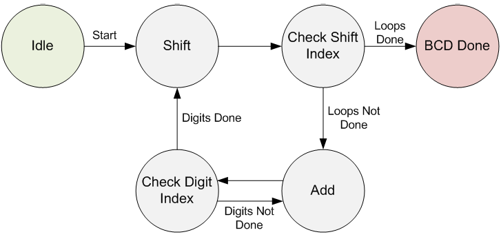
The Double Dabble Algorithm is described in detail on the linked Wikipedia page. But basically it takes the input binary number as a start. It shifts it one bit at a time into the BCD output vector. It then looks at each 4-bit BCD digit independently. If any of the digits are greater than 4, that digit is incremented by 3. This loop continues for each bit in the input binary vector. See the image below for a visual depiction of how the Finite State Machine is written.

Double Dabble Finite State Machine