内容介绍
内容介绍
所选任务介绍
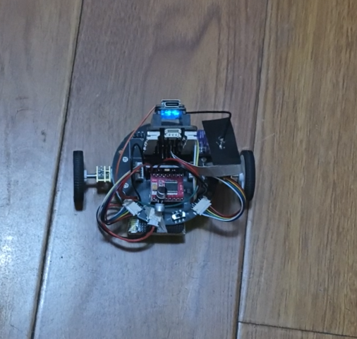
AI自平衡巡航车
项目介绍
- 使用ESP32-S3的双核处理功能,一个核用于直立环、速度环运行,一个核用于图像识别。
- 六轴传感器mpu6500实时估计车体俯仰角,完成两轮自平衡控制,可稳定站立并实现前后移动。
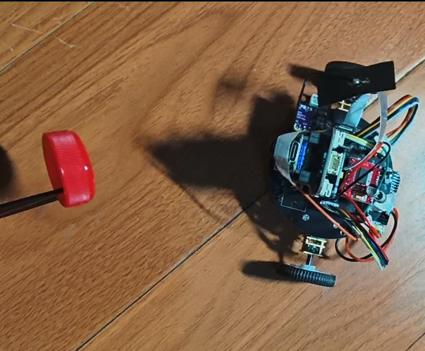
- 摄像头实现平衡状态下的目标跟随,追踪红色瓶盖,图像识别使用Edge Impulse训练模型。
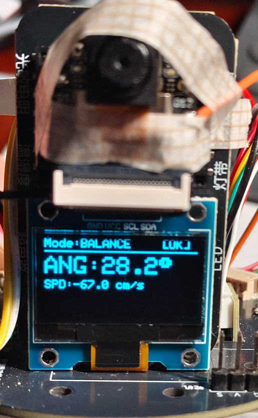
- OLED显示当前角度、速度与模式。
简短的所有使用到的硬件介绍
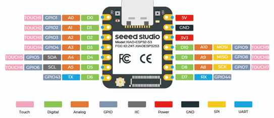
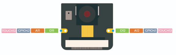
Seeed XIAO ESP32-S3 Sense
- 集成 ESP32S3 32 位双核 Xtensa 处理器芯片,运行频率高达 240 MHz,支持 Arduino / MicroPython;
- OV2640 摄像头传感器,分辨率 1600x1200;
- 提供 8MB PSRAM 和 8MB FLASH,支持 SD 卡插槽用于外部 32GB FAT 存储;
- 支持 2.4GHz Wi-Fi 和 BLE 双无线通信;
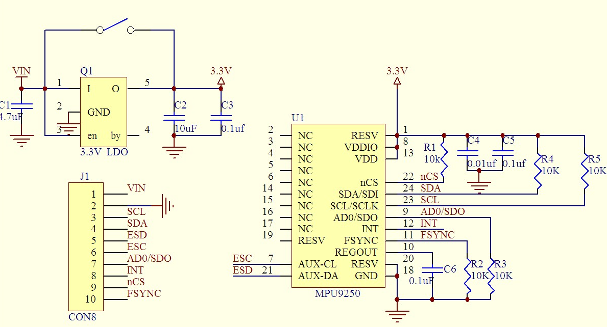
MPU6500
集成3轴陀螺仪和3轴加速度计,用于检测物体的姿态、角速度和加速度。
- 通信接口:I2C
- 陀螺仪量程:±250°/s 至 ±2000°/s
- 加速度计量程:±2g 至 ±16g
- 工作电压:3.3V
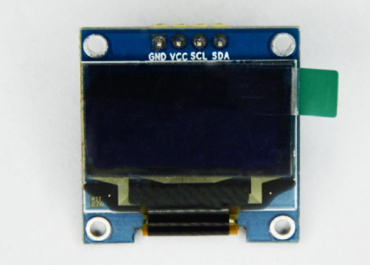
OLED
通信协议IIC,SSD131590,128x64
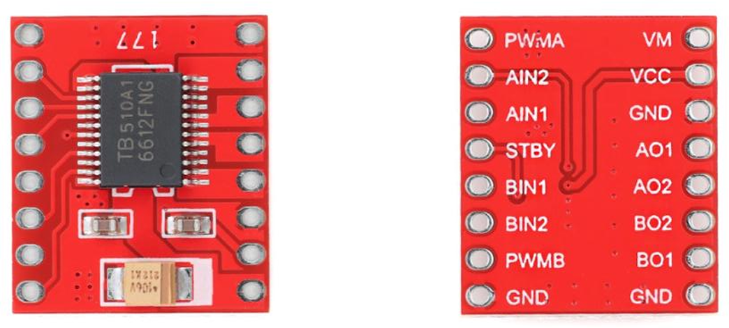
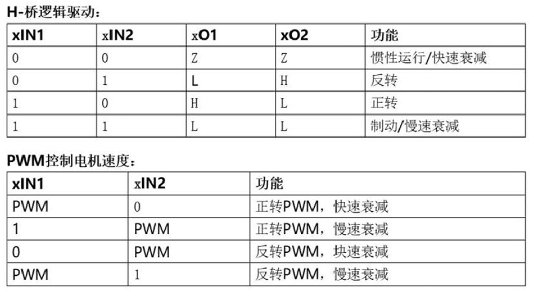
电机驱动TB6612
双路直流电机驱动芯片,可同时驱动两个直流电机。
控制信号:方向控制(DIRx) + PWM调速(PWMx)。
电机编码器
霍尔磁性编码器(输出AB相正交脉冲)。
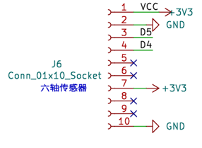
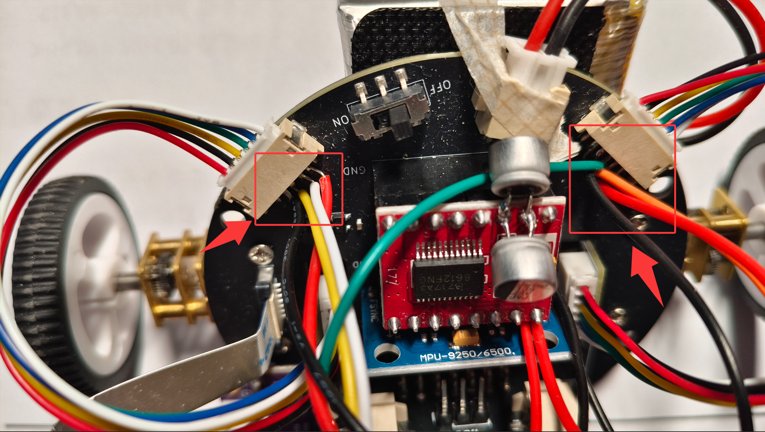
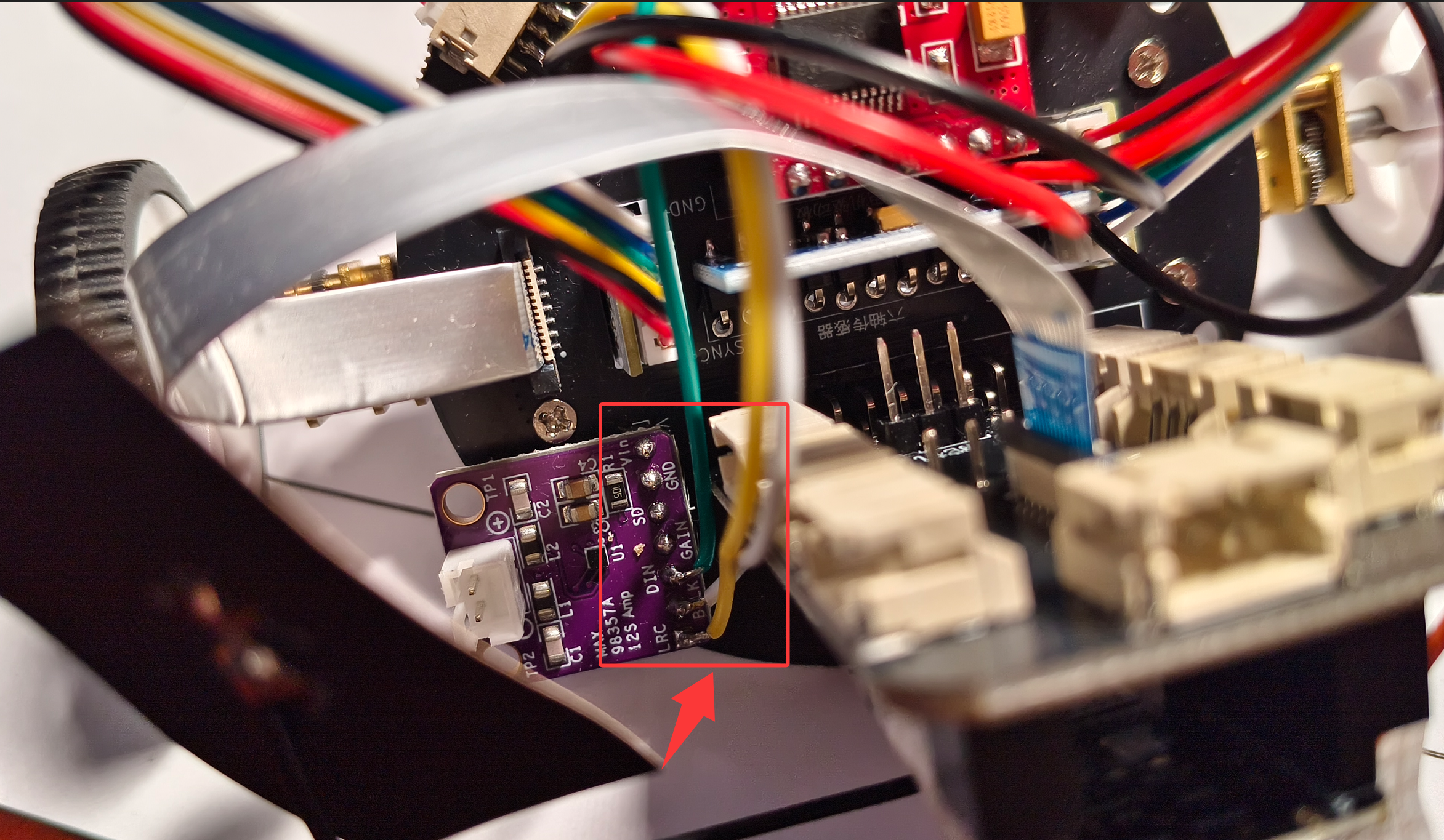
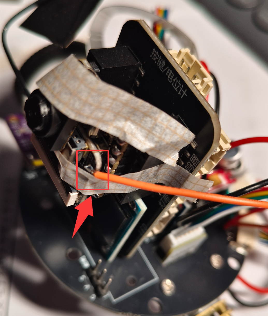
注意,本小车底板没有为编码器供电,ESP32也没有连接到电机编码器AB相线,所以无法实现平衡小车速度环。
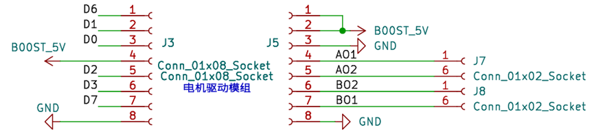
本工程采用飞线方式为电机编码器供电,以及采集电机编码器信号,连接方式如下:电机编码器小板供电引脚飞线到MPU6500模块电源引脚上,正交编码信号分别连接到D9、D10;D8、D12上
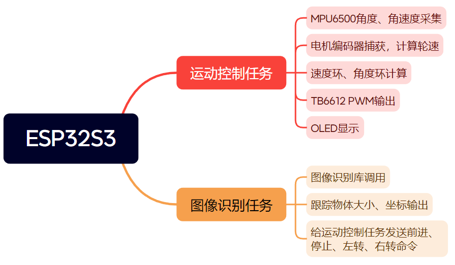
方案框图和项目设计思路介绍
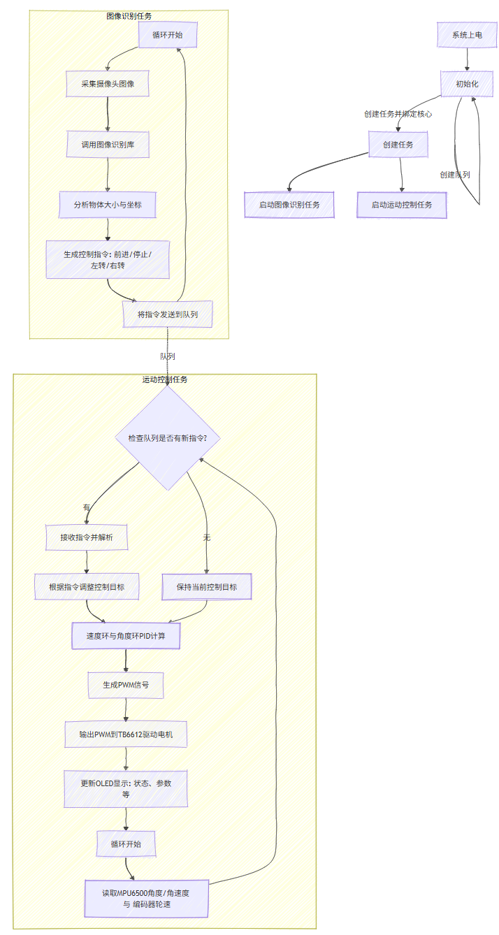
- 运动控制任务运行在esp32核心1,该任务持续采集MPU6500的倾角与角速度数据,结合电机编码器反馈的轮速,进行速度环与角度环的双层PID计算,最终计算出驱动指令并通过TB6612输出PWM控制电机,同时将关键状态信息刷新到OLED显示屏上。
- 图像识别任务运行在esp32核心0,该任务通过调用图像识别库分析摄像头画面,实时计算出被跟踪物体的大小与坐标,并据此生成平衡小车控制指令:前进、停止、左转、右转。通过队列将指令发送给运动控制任务,从而实现平衡小车自动跟踪物体功能。
软件流程图及关键代码介绍
调试软件:Arduino
编程语言:C、C++
速度环代码:
- 通过低通滤波融合MPU6500的倾角与Y轴陀螺仪角速度数据,获取车身当前姿态与变化趋势。
- 读取两个电机的编码器脉冲差值,并经过滤波计算出当前平均车速。
- 基于反馈数据,程序执行速度环PID控制:以目标速度为基准,计算比例与积分输出,输出一个用于角度环平衡的补偿量。
// 读取MPU数据
    gyr = myMPU6500.getGyrValues();
    angle = myMPU6500.getAngles();


    current_angle = angle.z * 0.2 + current_angle*0.8;
    derivative = gyr.y * 0.2 + derivative*0.8;  // 直接使用Y轴陀螺仪
    current_angle = angle.z;
    derivative = gyr.y;


    // 读取编码器
    static int32_t left_count;
    static int32_t right_count;


    left_count = encoder.getCount();
    right_count = -encoder2.getCount();


    // 计算编码器速度  电机转一圈输出14个脉冲,减速比50
    float  left_speed_raw  = (left_count - last_left_count) ;   //速度脉冲数
    float  right_speed_raw  = (right_count - last_right_count);
    last_left_count = left_count;
    last_right_count = right_count;


    static float left_speed_filtered = 0, right_speed_filtered = 0;


    left_speed_filtered  = 0.3 * left_speed_raw + 0.7 * left_speed_filtered;        //dt时间内脉冲差值
    right_speed_filtered  = 0.3 * right_speed_raw + 0.7 * right_speed_filtered;


    // 计算平均速度, 单位:cm/s
    actual_speed  = (left_speed_raw + right_speed_raw) / 2.0f;
    filteredSpeed = filteredSpeed * 0.8 + 0.2 * actual_speed;


    // 计算速度误差
    speed_error = Speed_offset - (filteredSpeed + derivative * 0.1f);
    static float speed_integral = 0;
    float speed_Kp = 0.25f;
    float speed_Ki = 0.01f;


    if (abs(current_angle) <= 30.0f) {
      // 比例项
      float p_out = speed_Kp * speed_error;


      if (abs(speed_error) > 0.0f) {
          speed_integral += speed_error * CONTROL_PERIOD;  // 积分需要乘以时间
          speed_integral = constrain(speed_integral, -5.0f, 5.0f);
      }
      float i_out = speed_Ki * speed_integral;


      // 速度环总输出 = 角度偏移量
      angle_offset = p_out + i_out;


      angle_offset = constrain(angle_offset, -2.50, 2.50);
    } else {
        // 角度过大,重置速度环
        angle_offset = 0.0f;
        speed_integral = 0.0f;
    }
直立环代码:
- 对速度环计算出的angle_offset进行平滑滤波,将其作为平衡角度的动态补偿;
- 直立环通过PD控制器计算保持小车平衡所需的电机pwm输出,接着为左右电机叠加转向控制量,并周期性地调用显示更新函数。
static float angle_offset_last = 0.0;
    angle_offset = 0.5 * angle_offset + 0.5 * angle_offset_last;
    angle_offset_last = angle_offset;


    if ((abs(current_angle) <= 30) ) {                    //如果小车前后倾斜角度小于30°
      error = current_angle - 1.8 - angle_offset;         //计算小车偏转角度与静态平衡角度的差值
      integral += error;
      integral = constrain(integral, -100, 100);
      balance_output = 10 * error + 0.000 * integral + 0.3 * derivative; //通过调节PID计算角度环PWM数值
    }
    else balance_output = 0;


    // 计算最终电机输出
    left_output = balance_output - turn_offset;
    right_output = balance_output + turn_offset;


    if(left_output > 0) left_output += 8;
    else if(left_output < 0) left_output -= 8;


    if(right_output > 0) right_output += 5;
    else if(right_output < 0) right_output -= 5;


    static float left_prev = 0, right_prev = 0;


    float left_max_change = 50.0;
    float right_max_change = 50.0;


    if (fabs(left_output - left_prev) > left_max_change) {
        left_output = left_prev + ((left_output > left_prev) ? left_max_change : -left_max_change);
    }
    if (fabs(right_output - right_prev) > right_max_change) {
        right_output = right_prev + ((right_output > right_prev) ? right_max_change : -right_max_change);
    }

    left_prev = left_output;
    right_prev = right_output;


    // 限幅
    left_output = constrain(left_output, -85, 85);
    right_output = constrain(right_output, -85, 85);


    // 控制电机
    motor_control.motor(left_output, right_output);


    static unsigned int task_5ms = 0;
    task_5ms ++ ;


    if(task_5ms % 20){
      updateDisplay();
    }
图像训练以及部署:
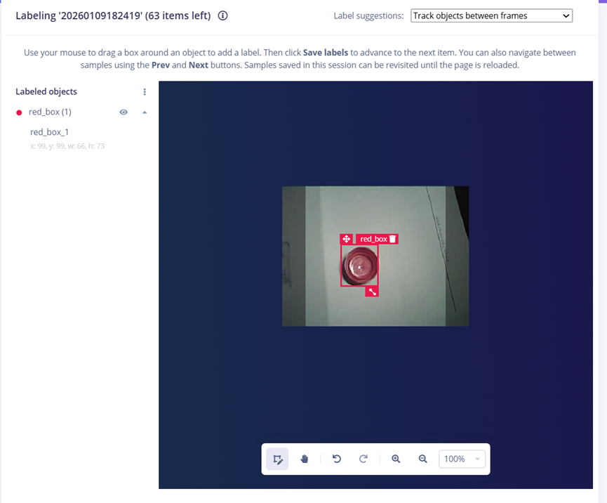
采集多张红色瓶盖的图片,在edge impulse中进行对象标注:
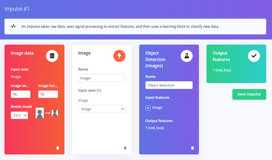
在Create Impulse中配置如下,右上角选择芯片型号:
在Image页面,点击Save Parameter:
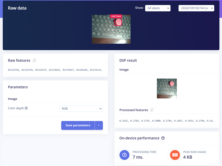
点击Generate features后,生成图像特征:
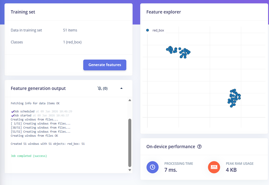
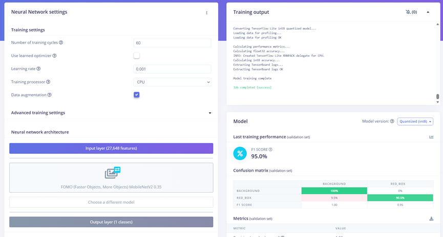
最后在Object detection界面,点击Save & train实现模型训练,训练完成后可以看到模型在测试集上的效果
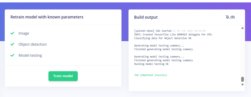
接着Retrain model
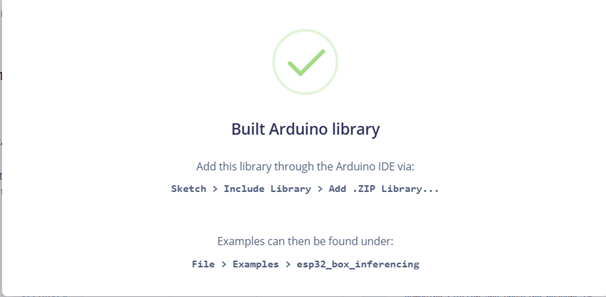
在Deployment中,选择Deployment为Arduino library,选择Model Optimizations为TensorFlow Lite,最后生成该模型

生成模型后,将模型解压到arduino -> libraries路径下
物体跟随控制逻辑:
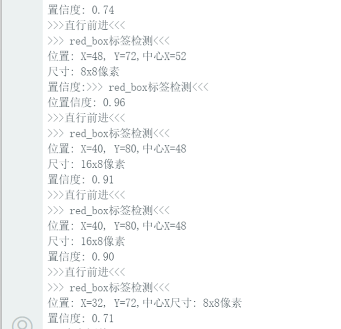
- 图像识别任务捕获一帧摄像头图像,然后调用Edge Impulse机器学习框架的模型进行分类与目标检测,并特别筛选标签为red_box的识别结果。
- 系统根据该目标在画面中的位置(X坐标)和尺寸(宽度与高度)进行决策:若尺寸过大则指令停止,若目标偏左或偏右则分别生成小幅度的转向指令,若目标居中则指令前进,若未检测到目标则指令停止。
- 生成的速度与转向偏移指令通过消息队列发送给运动控制任务,从而实现基于视觉的自动跟踪。
void imageProcessingTask(void *parameter) {
    TickType_t lastWakeTime = xTaskGetTickCount();
    const TickType_t taskDelay = pdMS_TO_TICKS(400); // 500ms延时


    DataPacket_t data;


    while (1) {

    vTaskDelayUntil(&lastWakeTime, taskDelay);


    snapshot_buf = (uint8_t*)malloc(EI_CAMERA_RAW_FRAME_BUFFER_COLS * EI_CAMERA_RAW_FRAME_BUFFER_ROWS * EI_CAMERA_FRAME_BYTE_SIZE);


    // check if allocation was successful
    if(snapshot_buf == nullptr) {
        ei_printf("ERR: Failed to allocate snapshot buffer!\n");
        continue;
    }


    ei::signal_t signal;
    signal.total_length = EI_CLASSIFIER_INPUT_WIDTH * EI_CLASSIFIER_INPUT_HEIGHT;
    signal.get_data = &ei_camera_get_data;


    if (ei_camera_capture((size_t)EI_CLASSIFIER_INPUT_WIDTH, (size_t)EI_CLASSIFIER_INPUT_HEIGHT, snapshot_buf) == false) {
        ei_printf("Failed to capture image\r\n");
        free(snapshot_buf);
        continue;
    }


    // Run the classifier
    ei_impulse_result_t result = { 0 };


    EI_IMPULSE_ERROR err = run_classifier(&signal, &result, debug_nn);
    if (err != EI_IMPULSE_OK) {
        ei_printf("ERR: Failed to run classifier (%d)\n", err);
        continue;
    }


    // // print the predictions
    // ei_printf("Predictions (DSP: %d ms., Classification: %d ms., Anomaly: %d ms.): \n",
    //             result.timing.dsp, result.timing.classification, result.timing.anomaly);


    bool blue_detected = false;


#if EI_CLASSIFIER_OBJECT_DETECTION == 1
    // ei_printf("Object detection bounding boxes:\r\n");
    for (uint32_t i = 0; i < result.bounding_boxes_count; i++) {
        ei_impulse_result_bounding_box_t bb = result.bounding_boxes[i];
        if (bb.value == 0) {
            continue;
        }
        // ei_printf("  %s (%f) [ x: %u, y: %u, width: %u, height: %u ]\r\n",
        //         bb.label,
        //         bb.value,
        //         bb.x,
        //         bb.y,
        //         bb.width,
        //         bb.height);


    // 检测到Blue标签时的控制逻辑
        if (strcmp(bb.label, "red_box") == 0)
        {
            blue_detected = true;
            // 获取坐标和尺寸信息
            uint32_t x = bb.x;
            uint32_t y = bb.y;
            uint32_t width = bb.width;
            uint32_t height = bb.height;
            uint32_t center_x = x + width / 2;
            Serial.printf(">>> red_box标签检测<<<\n");
            Serial.printf("位置: X=%u, Y=%u,中心X=%u\n", x, y, center_x);
            Serial.printf("尺寸: %ux%u像素\n", width, height);
            Serial.printf("置信度: %.2f\n", bb.value);
            // 检查尺寸条件-如果长或宽超过40,停止
            if (width > 80 || height > 80)
            {
                Serial.printf("***尺寸过大,停止移动***\n");
                data.turn_offset = 0;
                data.Speed_offset = 0.0;
            }
            // 根据X坐标调整方向
            else if (x < 35)
            {
                Serial.printf(">>>向左调整<<<\n");
                data.turn_offset = 5;
                data.Speed_offset = 0.0;
            }
            else if (x > 70)
            {
                Serial.printf(">>>向右调整<<<\n");
                data.turn_offset = -5;
                data.Speed_offset = 0.0;
            }
            else
            {
                Serial.printf(">>>直行前进<<<\n");
                data.turn_offset = 0;
                data.Speed_offset = 10.0;
            }


        }
    }


    // 如果没有检测到Blue标签,停止电机
    if (!blue_detected)
    {
        Serial.printf("未检测到red_box标签,停止\n");
        data.turn_offset = 0;
        data.Speed_offset = 0.0;

    }


    if (xQueueSend(dataQueue, &data, pdMS_TO_TICKS(10)) != pdTRUE) {
        Serial.println("队列已满,数据未发送");
    }
    // Print the prediction results (classification)
#else
    ei_printf("Predictions:\r\n");
    for (uint16_t i = 0; i < EI_CLASSIFIER_LABEL_COUNT; i++) {
        ei_printf("  %s: ", ei_classifier_inferencing_categories[i]);
        ei_printf("%.5f\r\n", result.classification[i].value);
    }
#endif


    // Print anomaly result (if it exists)
#if EI_CLASSIFIER_HAS_ANOMALY
    ei_printf("Anomaly prediction: %.3f\r\n", result.anomaly);
#endif


    #if EI_CLASSIFIER_HAS_VISUAL_ANOMALY
        ei_printf("Visual anomalies:\r\n");
        for (uint32_t i = 0; i < result.visual_ad_count; i++) {
            ei_impulse_result_bounding_box_t bb = result.visual_ad_grid_cells[i];
            if (bb.value == 0) {
                continue;
            }
            ei_printf("  %s (%f) [ x: %u, y: %u, width: %u, height: %u ]\r\n",
                    bb.label,
                    bb.value,
                    bb.x,
                    bb.y,
                    bb.width,
                    bb.height);
        }
    #endif


    free(snapshot_buf);
    }
}
OLED界面显示:
- 屏幕顶部显示当前控制模式(如平衡、前进或转向);
- 中部显示车身的绝对倾角;
- 底部显示由编码器计算出的实时速度。
void updateDisplay() {
  display.clearDisplay();

  // 第一部分:标题栏 (显示模式和状态)
  display.setTextSize(1);
  display.setCursor(0, 0);
  display.print("Mode:");
  switch(controlMode) {
    //0-平衡, 1-前进, 2-左转,3-右转
    case 0: display.print("BALANCE"); break;
    case 1: display.print("Forward"); break;
    case 2: display.print("LEFT"); break;
    case 3: display.print("RIGHT"); break;
    default: display.print("UNKNOWN");
  }

  // 在右上角显示状态
  display.setCursor(SCREEN_WIDTH - 30, 0);
  if(systemStatus == 1) {
    display.print("[OK]");
  } else {
    display.print("[ERR]");
  }


  // 第二部分:角度显示 (大字体,居中)
  display.drawLine(0, 10, SCREEN_WIDTH, 10, SSD1306_WHITE); // 分隔线

  display.setTextSize(2);
  display.setCursor(0, 15);
  display.print("ANG:");
  display.print(abs(current_angle), 1); // 显示绝对值,1位小数
  display.print((char)247); // 显示度符号 °


  //速度
  display.setTextSize(1);
  display.setCursor(0, 35);
  display.print("SPD:");
  display.print(actual_speed, 1); // 转换为cm/s显示
  display.print(" cm/s");


  // 将所有内容输出到屏幕
  display.display();
}
功能展示图及说明
oled界面显示当前角度、轮速:
小车保持平衡:
Arduino串口界面输出图像识别捕获“”红色瓶盖“信息:
小车跟踪红色瓶盖:
项目中遇到的难题及解决方法
- 平衡小车底板没有给电机编码器供电,也没有采集AB相输出,意味着无法实现速度环,几经想要放弃平衡小车这个工程,挤破头脑通过飞线实现esp32 xiao引脚数不够的难题。
- 图像识别率低:起初红色瓶盖图像样本只有50张,训练并部署后发现识别率很低,后面增加样本数量到200,部署后识别率增加。
- 直立环小车无法保持平衡:小车自身不平衡,通过移动电池位置配平,同时程序中需要增加一个补偿角度。
心得体会
- 第一次接触edge impulse,用户只要上传样本,系统就会自动训练,部署也很方便。
- 之前接触过平衡小车的理论,但从未亲手做过,很感谢电子森林这个平台,提供这么一个机会,让理论变在实物中得到应用。
附件下载

BalanceCarTracking_release.zip
团队介绍
个人
评论
0 / 100
查看更多
猜你喜欢
制作FPGA电子琴1. 存储一段音乐,并可以进行音乐播放,
2. 可以自己通过板上的按键进行弹奏,支持两个按键同时按下(和弦)并且声音不能失真,板上的按键只有13个,可以通过有上方的“上“、”下”两个按键对音程进行扩展
2714
2026寒假练 - 基于人工智能硬件实验套件平台实现智能门禁与报警系统本项目是一款融合了物联网(IoT)与边缘人工智能(Edge AI)的综合性安防终端。系统以 XIAO ESP32-S3 Sense 为主控核心,打破了传统门禁依赖云端服务器比对的延迟与隐私泄露痛点。
371
2026寒假练 – 基于人工智能硬件实验套件平台实现智能语音氛围灯带该项目使用了人工智能硬件实验套件平台,实现了智能语音氛围灯带的设计,它的主要功能为:1. 设计3种氛围灯显示模式,要求灯珠在一定周期内存在连续变化,例如跑马灯、彩虹灯、呼吸灯等。2. 在 OLED 上显示当前模式、亮度及速度。3. 在执行开关灯、模式切换、速度、亮度切换时,都使用蜂鸣器短鸣进行提示。4. 使用麦克风外部输入,通过AI模型实现设备控制。。
138
