任务介绍
本次选择的任务是做一款可以输出三轴数据的模块,具体任务如下:
设计一款IMU模块:设计一款IMU模块,可实现至少三轴的数据检测,例如加速度计、陀螺仪、磁力计等;
板卡尺寸:小于60mmx40mm;
包含信号:信号输出口,+3.3V、GND;
主要器件:需在DigiKey官网上有货且正常售卖。
我们本次选择的传感器是LIS2DW12三轴加速度传感器,该款传感器也是在得捷上呗广泛应用的模块,相关软件内容也是比较齐全的,便于后续的调试。
硬件介绍
本次设计的模块主要基于LIS2DW12进行设计,LIS2DW12三轴加速度计是一款性能全面且优良的线性加速度模块,它具有16位数据输出、1.6~1.6KHz带宽、±2/4/8/16g的可选量程、低功耗(低至50nA)、低噪音(低至1.3mgRMS)、32级FIFO的优点。且该产品拥有两个独立的可编程中断及专用内部引擎,使得该产品可实现超多功能,例如获取三轴加速度、自由落体检测、自由落体中断、纵向/横向检测、朝向检测(6D/4D)、可配置的单击/双击识别、敲击中断、运动检测、运动唤醒以实现高级省电等。
基本特性如下:
工作电压:3.3V
工作电流:50nA(低功耗模式)/0.17mA(高性能模式)
接口方式:I2C/SPI
I2C地址:0x19(默认地址)/0x18(可选:SDO引脚拉低选中)
可选量程:±2g/±4g/±8g/±16g
工作温度范围:-40℃~+85℃
16位数据输出
频率/带宽:1.6Hz~1600Hz
超低噪声:1.3mgRMS(低功耗模式)。
设计思路
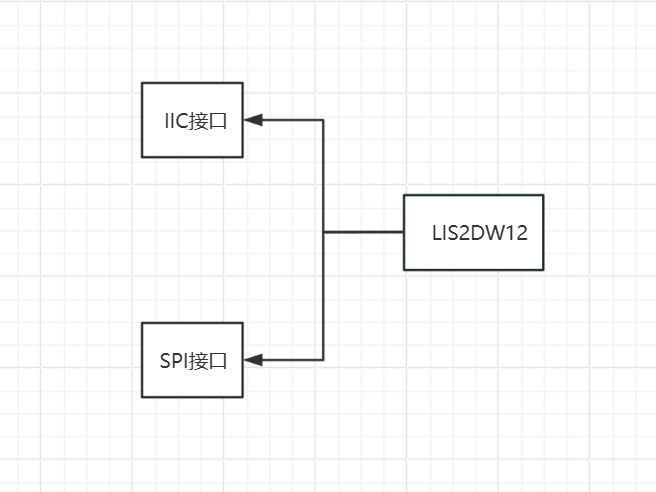
本次主要设计一款三轴加速度计模块,主要还是常用的IIC接口通信,同时进行兼容SPI接口,在硬件上做一下兼容,整体的组成如下:
模块介绍
本次设计的三轴加速度计模块主要基于LIS2DW12进行设计,LIS2DW12三轴加速度计是一款超低功耗的线性加速度计,该传感器拥有两个独立的可编程中断及专用内部引擎,可实现超多功能,例如自由落体检测、纵向/横向检测、朝向检测、可配置的单击/双击识别、运动检测、运动唤醒以实现高级省电等。
原理图和PCB模块介绍
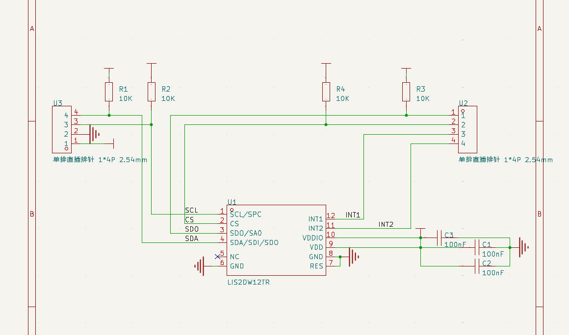
原理图

PCB
本次的设计采用的是插针连接的方式,基本上把引脚和状态引脚引出来了,如果进行简单的应用只要用U3引脚内容就可以进行基本的通信,配置U2引脚的中断可以实现更多的实时性强的设计,模块比较小巧,我们参考了一些经典设计,留有4个定位孔用于安装固定。

实物效果图
模块调试
我们本次的调试主要是基于DFRobot的资源进行,主要也是为了能够快速验证硬件平台,我们选用的是Arduino进行软件编程,首先我们要下载DFRobot基于三轴的库文件,可以参考附件的库文件,然后选择器应用,这里我们选择的是方向检测,代码如下:
#include <DFRobot_LIS2DW12.h>

//DFRobot_LIS2DW12_I2C acce(&Wire,0x18);
DFRobot_LIS2DW12_I2C acce;

//When using SPI communication, use the following program to construct an object by DFRobot_LIS2DW12_SPI
#if defined(ESP32) || defined(ESP8266)
#define LIS2DW12_CS  D3
#elif defined(__AVR__) || defined(ARDUINO_SAM_ZERO)
#define LIS2DW12_CS 3
#elif (defined NRF5)
#define LIS2DW12_CS 2  //The pin on the development board with the corresponding silkscreen printed as P2
#endif

//DFRobot_LIS2DW12_SPI acce(/*cs = */LIS2DW12_CS,&SPI);
//DFRobot_LIS2DW12_SPI acce(/*cs = */LIS2DW12_CS);

int lastOrientation = 0; //No event happened

void setup(void){

  Serial.begin(9600);
  while(!acce.begin()){
     Serial.println("Communication failed, check the connection and I2C address setting when using I2C communication.");
     delay(1000);
  }
  Serial.print("chip id : ");
  Serial.println(acce.getID(),HEX);
  //Chip soft reset
  acce.softReset();

  /**!
    Set the sensor measurement range:
                   e2_g   /<±2g>/
                   e4_g   /<±4g>/
                   e8_g   /<±8g>/
                   e16_g  /< ±16g>/
  */
  acce.setRange(DFRobot_LIS2DW12::e2_g);

  /**!
   Set power mode:
       eHighPerformance_14bit         /<High-Performance Mode,14-bit resolution>/
       eContLowPwr4_14bit             /<Continuous measurement,Low-Power Mode 4(14-bit resolution)>/
       eContLowPwr3_14bit             /<Continuous measurement,Low-Power Mode 3(14-bit resolution)>/
       eContLowPwr2_14bit             /<Continuous measurement,Low-Power Mode 2(14-bit resolution)/
       eContLowPwr1_12bit             /<Continuous measurement,Low-Power Mode 1(12-bit resolution)>/
       eSingleLowPwr4_14bit           /<Single data conversion on demand mode,Low-Power Mode 4(14-bit resolution)>/
       eSingleLowPwr3_14bit           /<Single data conversion on demand mode,Low-Power Mode 3(14-bit resolution)>/
       eSingleLowPwr2_14bit           /<Single data conversion on demand mode,Low-Power Mode 2(14-bit resolution)>/
       eSingleLowPwr1_12bit           /<Single data conversion on demand mode,Low-Power Mode 1(12-bit resolution)>/
       eHighPerformanceLowNoise_14bit /<High-Performance Mode,Low-noise enabled,14-bit resolution>/
       eContLowPwrLowNoise4_14bit     /<Continuous measurement,Low-Power Mode 4(14-bit resolution,Low-noise enabled)>/
       eContLowPwrLowNoise3_14bit     /<Continuous measurement,Low-Power Mode 3(14-bit resolution,Low-noise enabled)>/
       eContLowPwrLowNoise2_14bit     /<Continuous measurement,Low-Power Mode 2(14-bit resolution,Low-noise enabled)>/
       eContLowPwrLowNoise1_12bit     /<Continuous measurement,Low-Power Mode 1(12-bit resolution,Low-noise enabled)>/
       eSingleLowPwrLowNoise4_14bit   /<Single data conversion on demand mode,Low-Power Mode 4(14-bit resolution),Low-noise enabled>/
       eSingleLowPwrLowNoise3_14bit   /<Single data conversion on demand mode,Low-Power Mode 3(14-bit resolution),Low-noise enabled>/
       eSingleLowPwrLowNoise2_14bit   /<Single data conversion on demand mode,Low-Power Mode 2(14-bit resolution),Low-noise enabled>/
       eSingleLowPwrLowNoise1_12bit   /<Single data conversion on demand mode,Low-Power Mode 1(12-bit resolution),Low-noise enabled>/
  */
  acce.setPowerMode(DFRobot_LIS2DW12::eContLowPwrLowNoise1_12bit);

  /**!
    Set the sensor data collection rate:
               eRate_0hz           /<Measurement off>/
               eRate_1hz6          /<1.6hz, use only under low-power mode>/
               eRate_12hz5         /<12.5hz>/
               eRate_25hz
               eRate_50hz
               eRate_100hz
               eRate_200hz
               eRate_400hz       /<Use only under High-Performance mode>/
               eRate_800hz       /<Use only under High-Performance mode>/
               eRate_1k6hz       /<Use only under High-Performance mode>/
               eSetSwTrig        /<The software triggers a single measurement>/
  */
  acce.setDataRate(DFRobot_LIS2DW12::eRate_200hz);

  /**!
    Set the threshold of the angle when turning:
                     eDegrees80   (80°)
                     eDegrees70   (70°)
                     eDegrees60   (60°)
                     eDegrees50   (50°)
  */
  acce.set6DThreshold(DFRobot_LIS2DW12::eDegrees60);

  /**!
    Set the interrupt source of the int1 pin:
    eDoubleTap(Double click)
    eFreeFall(Free fall)
    eWakeUp(wake)
    eSingleTap(single-Click)
    e6D(Orientation change check)
  */
  acce.setInt1Event(DFRobot_LIS2DW12::e6D);

  delay(1000);
}

void loop(void){
    //check Changes detected in six directions
    if(acce.oriChangeDetected()){
        DFRobot_LIS2DW12::eOrient_t orientation = acce.getOrientation();
        if(lastOrientation != orientation){
            if(orientation == DFRobot_LIS2DW12::eXDown){
             Serial.println("X is down now");
            }
            if(orientation == DFRobot_LIS2DW12::eXUp){
             Serial.println("X is up now");
            }
            if(orientation == DFRobot_LIS2DW12::eYDown){
             Serial.println("Y is down now");
            }
            if(orientation == DFRobot_LIS2DW12::eYUp){
             Serial.println("Y is up now");
            }
            if(orientation == DFRobot_LIS2DW12::eZDown){
             Serial.println("Z is down now");
            }
            if(orientation == DFRobot_LIS2DW12::eZUp){
             Serial.println("Z is up now");
            }
            lastOrientation = orientation;
        }
    }
}
串口打印效果如下:

心得体会
这次我们设计的是一个三轴的模块,实际上有很多厂家的产品,ST绝对是一方巨头,也有很多的模块是基于这方面的传感器进行设计的,这次我们主要参考的事DFRobot的模块,有着丰富的软件开发教程,非常的方便!