
2025 Make Blocks综合项目 - 基于STM32G474与LAN9252的EtherCAT从站IO控制器
往期链接:2025 Make Blocks阶段2 - 基于STM32G474的核心板设计
2025 Make Blocks阶段1 - 基于LAN9252的Ethercat从站模块
一,任务介绍
本项目旨在设计一款高性能EtherCAT从站IO控制器,采用双板分离架构:
- 主控板:基于STM32G474CEU6,集成丰富外设(ST-Link/V2.1、CAN、RS485、USART、USB、扩展IO),负责应用层逻辑、本地IO处理及与扩展板的通信。
- EtherCAT扩展板:基于LAN9252 EtherCAT从站控制器,负责EtherCAT协议栈处理,通过SPI接口与主控板交换过程数据。
项目实现2路数字输入和2路数字输出,具备以下功能:
- 支持标准EtherCAT通信,可与倍福TwinCAT等主站无缝对接。
- 主控板提供多种工业接口(CAN、RS485、USB),便于功能扩展。
- 双板设计便于模块化复用:主控板可独立作为通用控制器,扩展板可适配不同MCU平台。
项目作为“2025 Make Blocks综合项目”的一部分,旨在通过实践融合嵌入式控制、工业通信等多领域知识。
二,模块介绍
1. 主控板(Base Board)
模块 | 主要器件 | 功能简介 | 选型理由 |
|---|---|---|---|
主控MCU | STM32G474CEU6 | 运行应用层代码,处理本地IO、通信协议,通过SPI与扩展板交换数据 | 内置HRTIM、CORDIC、FMAC,适合实时控制;LQFP100便于手工焊接 |
板载调试器 | ST-Link/V2.1(基于STM32F103CB) | 支持在线仿真、虚拟串口、拖拽下载 | 集成调试功能,无需外接仿真器 |
工业通信 | CAN(TJA1051TK/3/1)、RS485(SIT3088ETK)、USART,USB | 连接PLC、变频器、传感器等 | 覆盖主流工业总线,便于系统集成 |
USB接口 | USB Device(STM32内置) | 虚拟串口、固件升级 | 方便与PC通信 |
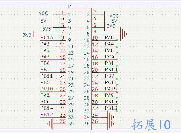
扩展IO | 排针引出剩余GPIO | 用户自定义扩展 | 提高灵活性 |
电源 | 24V转5V(RY8411)、5V转3.3V(XC6210B332MR) | 为板载芯片及扩展板供电 | 工业电压输入,两级降压稳定 |
2. EtherCAT扩展板(EtherCAT Slave Board)
模块 | 主要器件 | 功能简介 | 选型理由 |
|---|---|---|---|
EtherCAT从站控制器 | Microchip LAN9252 | 处理EtherCAT数据链路层,提供SPI从接口与主控通信 | 集成双PHY,简化设计;支持分布式时钟 |
物理层接口 | LAN9252内置PHY + RJ45(带网络变压器) | 连接EtherCAT网络(IN/OUT) | 内置PHY节省空间,变压器集成减小PCB面积 |
SPI接口 | 与主控板连接(SCK、MISO、MOSI、CS、IRQ) | 过程数据交换、寄存器配置 | 高速可靠,主控板支持 |
配置存储 | I2C EEPROM(BL24C64A-NTRC) | 存储从站设备信息(Vendor ID、Product Code等) | 标准从站设计 |
电源 | 从主控板取5V,5V转3.3V(XC6210B332MR) | 简化供电 | 双板通过排针连接 |
三,设计框图
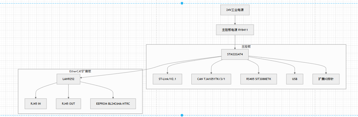
框图说明:
- 主控板以STM32G474为核心,通过SPI主接口连接扩展板的LAN9252从接口。
- 主控板独立处理本地数字输入输出,并通过SPI与扩展板交换过程数据(输入状态上传,输出指令下发)。
- 双板通过排针/排座连接,信号包括SPI(4线)、中断、5V/3.3V电源、GND。
四,原理图及PCB介绍
1,原理图介绍
主控板原理图关键设计
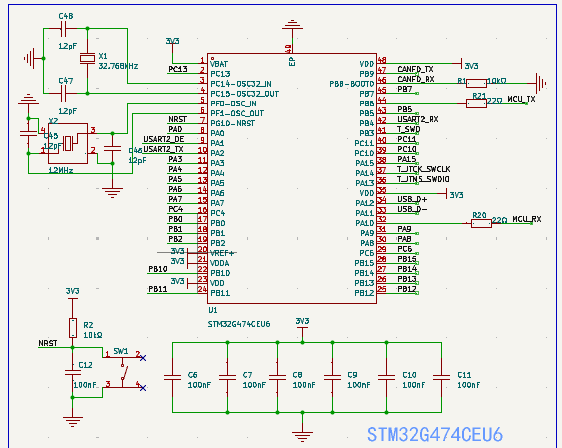
- 主控部分
采用STM32G474CEU6作为主控
- 电源部分
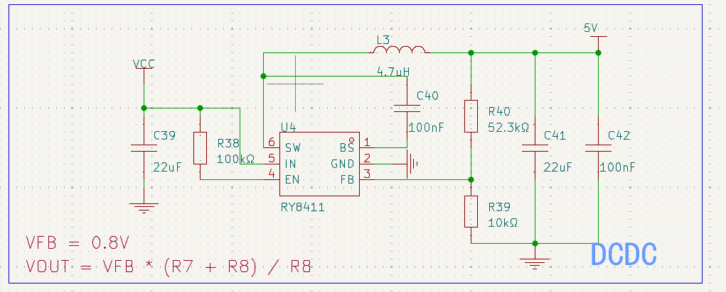
- 24V->5V采用RY8411,它具有4.5-40V宽输入范围 - 最大1A输出电流 - 过压/过流保护
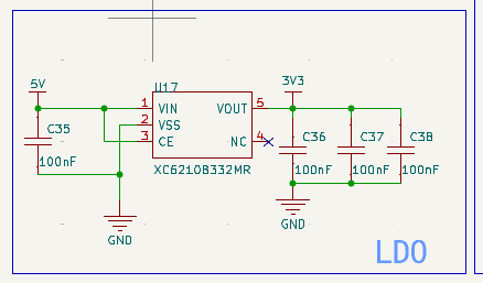
- 5V->3.3V采用XC6210B332MR
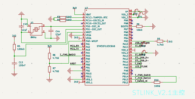
- ST_LINK_V2.1
采用stm32f103cbu6为主控
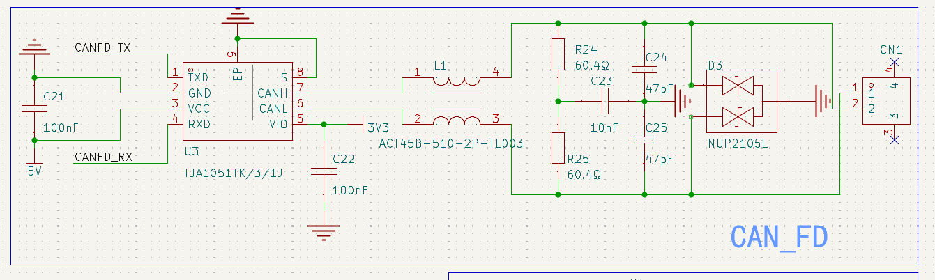
- CANFD
采用NXP的TJA1051TK/3/1收发器
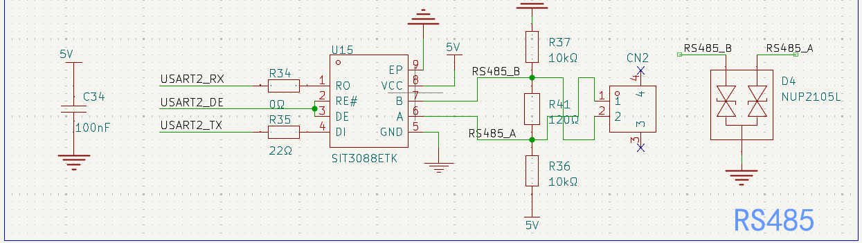
- RS485
采用SIT3088ETK
- 拓展IO
EtherCAT扩展板原理图关键设计
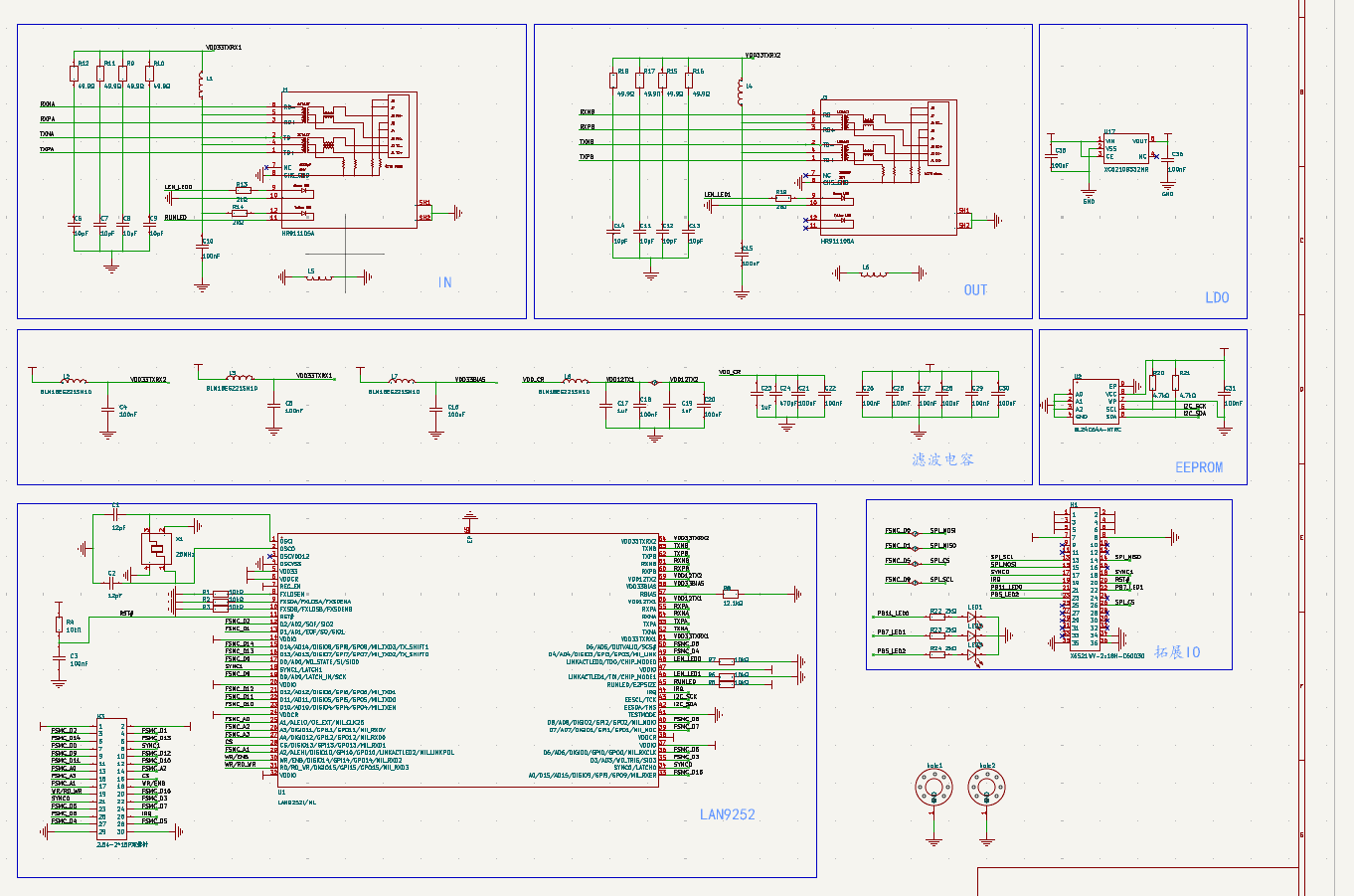
- LAN9252核心:25MHz晶振、SPI从接口、EEPROM接口(I2C)、中断输出。
- 以太网接口:
- RJ45带网络变压器(HR911105A),直接连接LAN9252的差分信号对。
- LED指示链路状态(由LAN9252驱动)。
- 电源:从主控板输入5V和3.3V,就近放置去耦电容。
2,PCB介绍
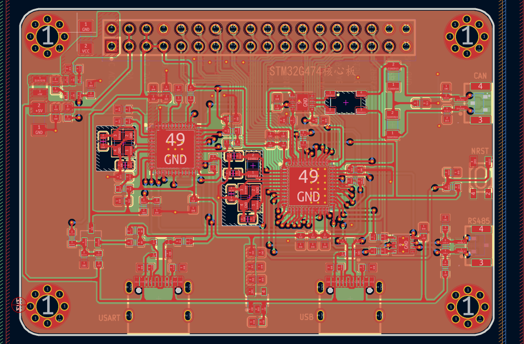
主控板PCB
EtherCAT扩展板PCB
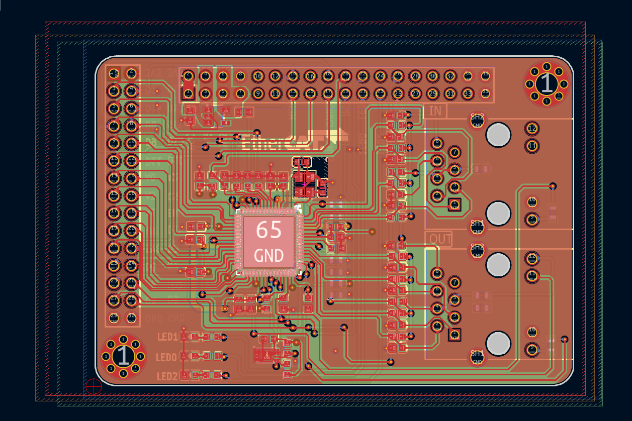
双板连接:主控板和扩展板通过双排2.54mm排针/排座堆叠连接
五,模块调试
调试软件介绍
- MCU开发:STM32CubeMX+MDK5,HAL库编程。
- EtherCAT主站:倍福TwinCAT 3用于扫描从站、配置PDO、监控状态。
- 从站协议栈:EtherCAT Slave Stack Code Tool生成基于LAN9252的从站代码,移植到STM32G474。
核心代码
接口修改
/*******************************************************************************
LAN9252 Hardware Abtraction Layer - Implementation file
Company:
Microchip Technology Inc.
File Name:
9252_HW.c
Description:
This file cContains the functional implementation of LAN9252 Hardware Abtraction Layer
Change History:
Version Changes
0.1 Initial version.
0.2 -
0.3 -
0.4 *Disabled Sync Manager & Application Layer Event Requests.
*Commented out the ISR call backs related to Sync Manager & AL Event Request.
1.0 *Enabled Sync Manager & Application Layer Event Requests.
*Added ISR call backs related to Sync Manager & AL Event Request.
*******************************************************************************/
/*******************************************************************************
Copyright (c) 2015 released Microchip Technology Inc. All rights reserved.
Microchip licenses to you the right to use, modify, copy and distribute
Software only when embedded on a Microchip microcontroller or digital signal
controller that is integrated into your product or third party product
(pursuant to the sublicense terms in the accompanying license agreement).
You should refer to the license agreement accompanying this Software for
additional information regarding your rights and obligations.
SOFTWARE AND DOCUMENTATION ARE PROVIDED AS IS WITHOUT WARRANTY OF ANY KIND,
EITHER EXPRESS OR IMPLIED, INCLUDING WITHOUT LIMITATION, ANY WARRANTY OF
MERCHANTABILITY, TITLE, NON-INFRINGEMENT AND FITNESS FOR A PARTICULAR PURPOSE.
IN NO EVENT SHALL MICROCHIP OR ITS LICENSORS BE LIABLE OR OBLIGATED UNDER
CONTRACT, NEGLIGENCE, STRICT LIABILITY, CONTRIBUTION, BREACH OF WARRANTY, OR
OTHER LEGAL EQUITABLE THEORY ANY DIRECT OR INDIRECT DAMAGES OR EXPENSES
INCLUDING BUT NOT LIMITED TO ANY INCIDENTAL, SPECIAL, INDIRECT, PUNITIVE OR
CONSEQUENTIAL DAMAGES, LOST PROFITS OR LOST DATA, COST OF PROCUREMENT OF
SUBSTITUTE GOODS, TECHNOLOGY, SERVICES, OR ANY CLAIMS BY THIRD PARTIES
(INCLUDING BUT NOT LIMITED TO ANY DEFENSE THEREOF), OR OTHER SIMILAR COSTS.
*******************************************************************************/
///////////////////////////////////////////////////////////////////////////////
// Included files
#include "ecat_def.h"
#include "main.h"
#ifdef PIC32_HW
#include <sys/attribs.h> /* For __ISR definition */
#endif
#include "ecatslv.h"
#include "main.h"
#define _9252_HW_ 1
#include "9252_HW.h"
#undef _9252_HW_
#define _9252_HW_ 0
#include "ecatappl.h"
#include "SPIDriver.h"
#include "stdio.h"
#define SYNC0_ACTIVE_LOW 0x01
#define SYNC1_ACTIVE_LOW 0x01
#ifndef PIC32_HW
#define PIC32_HW // Use PIC32MX board
#endif
///////////////////////////////////////////////////////////////////////////////
// Internal Type Defines
typedef union
{
unsigned short Word;
unsigned char Byte[2];
} UBYTETOWORD;
typedef union
{
UINT8 Byte[2];
UINT16 Word;
}
UALEVENT;
/*-----------------------------------------------------------------------------------------
------
------ LED defines
------
-----------------------------------------------------------------------------------------*/
#define LED_ECATRED LATDbits.LATD1
#ifndef PIC32_HW
BOOL bEscInterrupt = 0;
BOOL bSync0Interrupt = 0;
BOOL bSync1Interrupt = 0;
BOOL bTimer5Interrupt = 0;
///////////////////////////////////////////////////////////////////////////////
// Global Interrupt setting
#define DISABLE_GLOBAL_INT INTDisableInterrupts()
#define ENABLE_GLOBAL_INT INTEnableInterrupts()
#define DISABLE_AL_EVENT_INT DISABLE_GLOBAL_INT
#define ENABLE_AL_EVENT_INT ENABLE_GLOBAL_INT
///////////////////////////////////////////////////////////////////////////////
// ESC Interrupt
//0 - falling edge 1-
#define INIT_ESC_INT {(INTCONbits.INT0EP) = 0;(IPC0bits.INT0IP) = 7;}
#define ESC_INT_REQ (IFS0bits.INT0IF) //ESC Interrupt (INT0) state/flag
#define INT_EL (_RD0) //ESC Interrupt input port
#define EscIsr (_INT0Interrupt) // primary interrupt vector name
#define ACK_ESC_INT {(ESC_INT_REQ)=0;}
#define IS_ESC_INT_ACTIVE ((INT_EL) == 0) //0 - fro active low; 1 for hactive high
///////////////////////////////////////////////////////////////////////////////
// SYNC0 Interrupt
#ifndef RUN_FROM_SVB_FPGA
#define INIT_SYNC0_INT {(INTCONbits.INT1EP) = 0;(IPC1bits.INT1IP) = 5;}
#define SYNC0_INT_REQ (IFS0bits.INT1IF) //(_INT3IF) //Sync0 Interrupt (INT1) state
#define INT_SYNC0 (_RE8) //Sync1 Interrupt input port
#define Sync0Isr (_INT1Interrupt) // primary interrupt vector name
#define DISABLE_SYNC0_INT {IEC0bits.INT1IE=0;}//{(_INT1IE)=0;}//disable interrupt source INT1
#define ENABLE_SYNC0_INT {IEC0bits.INT1IE=1;} //enable interrupt source INT1
#define ACK_SYNC0_INT {(SYNC0_INT_REQ) = 0;}
#define SET_SYNC0_INT {(SYNC0_INT_REQ) = 1;}
#define SYNC0_INT_PORT_IS_ACTIVE {(INT_EL) == 0;}
#define IS_SYNC0_INT_ACTIVE ((INT_SYNC0) == 0) //0 - fro active low; 1 for hactive high
#define INIT_SYNC1_INT {(INTCONbits.INT2EP) = 0;(IPC2bits.INT2IP) = 4;}
#define SYNC1_INT_REQ (IFS0bits.INT2IF) //(_INT4IF) //Sync1 Interrupt (INT2) state
#define INT_SYNC1 (_RE9) //Sync1 Interrupt input port
#define Sync1Isr (_INT2Interrupt) // primary interrupt vector name
#define DISABLE_SYNC1_INT {IEC0bits.INT2IE=0;}//disable interrupt source INT2
#define ENABLE_SYNC1_INT {IEC0bits.INT2IE=1;} //enable interrupt source INT2
#define ACK_SYNC1_INT {(SYNC1_INT_REQ) = 0;}
#define SET_SYNC1_INT {(SYNC1_INT_REQ) = 1;}
#define SYNC1_INT_PORT_IS_ACTIVE {(INT_EL) == 0;}
#define IS_SYNC1_INT_ACTIVE ((INT_SYNC1) == 0) //0 - fro active low; 1 for hactive high
#else
// Place-holder
#endif
///////////////////////////////////////////////////////////////////////////////
// Hardware timer
#define STOP_ECAT_TIMER {(T5CONbits.TON) = 0; /*disable timer*/}
#define INIT_ECAT_TIMER { OpenTimer5(T5_ON | T5_IDLE_CON | T5_PS_1_256 | T5_SOURCE_INT, ECAT_TIMER_INC_P_MS);\
STOP_ECAT_TIMER\
(TMR5) = 0;/*clear timer register*/ }
#define START_ECAT_TIMER {(T5CONbits.TON) = 1; /*enable timer*/ }
#else
///////////////////////////////////////////////////////////////////////////////
// Global Interrupt setting
BOOL bEscInterrupt = 0;
BOOL bSync0Interrupt = 0;
BOOL bSync1Interrupt = 0;
BOOL bTimer5Interrupt = 0;
///////////////////////////////////////////////////////////////////////////////
// Global Interrupt setting
#define DISABLE_GLOBAL_INT __disable_irq()
#define ENABLE_GLOBAL_INT __enable_irq()
#define DISABLE_AL_EVENT_INT DISABLE_GLOBAL_INT
#define ENABLE_AL_EVENT_INT ENABLE_GLOBAL_INT
///////////////////////////////////////////////////////////////////////////////
// ESC Interrupt
//0 - falling edge 1-
#define INIT_ESC_INT
#define INT_EL HAL_GPIO_ReadPin(ECAT_IRQ_GPIO_Port,ECAT_IRQ_Pin) //ESC Interrupt input port
#define ACK_ESC_INT __HAL_GPIO_EXTI_CLEAR_IT(ECAT_IRQ_Pin)
#define IS_ESC_INT_ACTIVE ((INT_EL) == 0) //0 - fro active low; 1 for hactive high
///////////////////////////////////////////////////////////////////////////////
// SYNC0 Interrupt
#ifndef RUN_FROM_SVB_FPGA
#define INIT_SYNC0_INT
#define INT_SYNC0 HAL_GPIO_ReadPin(ECAT_SYNC0_GPIO_Port,ECAT_SYNC0_Pin) //Sync1 Interrupt input port
#define DISABLE_SYNC0_INT HAL_NVIC_DisableIRQ(ECAT_SYNC0_EXTI_IRQn)//{(_INT1IE)=0;}//disable interrupt source INT1
#define ENABLE_SYNC0_INT HAL_NVIC_EnableIRQ(ECAT_SYNC0_EXTI_IRQn) //enable interrupt source INT1
#define ACK_SYNC0_INT __HAL_GPIO_EXTI_CLEAR_IT(ECAT_SYNC0_Pin)
#define IS_SYNC0_INT_ACTIVE ((INT_SYNC0) == 0) //0 - fro active low; 1 for hactive high
#define INIT_SYNC1_INT
#define INT_SYNC1 HAL_GPIO_ReadPin(ECAT_SYNC1_GPIO_Port,ECAT_SYNC1_Pin) //Sync1 Interrupt input port
#define DISABLE_SYNC1_INT HAL_NVIC_DisableIRQ(ECAT_SYNC1_EXTI_IRQn)//disable interrupt source INT2
#define ENABLE_SYNC1_INT HAL_NVIC_EnableIRQ(ECAT_SYNC1_EXTI_IRQn) //enable interrupt source INT2
#define ACK_SYNC1_INT __HAL_GPIO_EXTI_CLEAR_IT(ECAT_SYNC1_Pin)
#define IS_SYNC1_INT_ACTIVE ((INT_SYNC1) == 0) //0 - fro active low; 1 for hactive high
#else
// Place-holder
#endif
///////////////////////////////////////////////////////////////////////////////
// Hardware timer
#define STOP_ECAT_TIMER HAL_TIM_Base_Stop_IT(&htim3)
#define INIT_ECAT_TIMER HAL_TIM_Base_Init(&htim3) //MX_TIM3_Init()//
#define START_ECAT_TIMER HAL_TIM_Base_Start_IT(&htim3)
#endif // end of PIC32_HW
///////////////////////////////////////////////////////////////////////////////
// Internal Variables
UALEVENT EscALEvent; // contains the content of the ALEvent register (0x220), this variable is updated on each Access to the Esc
UINT16 nAlEventMask; // current ALEventMask (content of register 0x204:0x205)
TSYNCMAN TmpSyncMan;
///////////////////////////////////////////////////////////////////////////////
// Internal functions
/*******************************************************************************
Function:
void GetInterruptRegister(void)
Summary:
The function operates a SPI access without addressing.
Description:
The first two bytes of an access to the EtherCAT ASIC always deliver the AL_Event register (0x220).
It will be saved in the global "EscALEvent"
*****************************************************************************/
static void GetInterruptRegister(void)
{
DISABLE_AL_EVENT_INT;
HW_EscReadIsr((MEM_ADDR *)&EscALEvent.Word, 0x220, 2);
ENABLE_AL_EVENT_INT;
}
/*******************************************************************************
Function:
void ISR_GetInterruptRegister(void)
Summary:
The function operates a SPI access without addressing.
Shall be implemented if interrupts are supported else this function is equal to "GetInterruptRegsiter()"
Description:
The first two bytes of an access to the EtherCAT ASIC always deliver the AL_Event register (0x220).
It will be saved in the global "EscALEvent"
*****************************************************************************/
static void ISR_GetInterruptRegister(void)
{
HW_EscReadIsr((MEM_ADDR *)&EscALEvent.Word, 0x220, 2);
}
///////////////////////////////////////////////////////////////////////////////
// Exported HW Access functions
/*******************************************************************************
Function:
UINT8 HW_Init(void)
Summary:
This function intialize the Process Data Interface (PDI) and the host controller.
Description:
*****************************************************************************/
#define USE_SPI
/*
* Ãè Êö£ºLAN9252_reset
* ¹¦ ÄÜ£º¸´Î»LAN9252´ËоƬ
* Èë¿Ú²ÎÊý£ºÎÞ
* ³ö¿Ú²ÎÊý£ºÎÞ
*/
void ECAT_reset(void)
{
HAL_GPIO_WritePin(ECAT_RES_GPIO_Port, ECAT_RES_Pin, GPIO_PIN_RESET);
HAL_Delay(10);
HAL_GPIO_WritePin(ECAT_RES_GPIO_Port, ECAT_RES_Pin, GPIO_PIN_SET);
HAL_Delay(10);
}
/*
* Ãè Êö£ºLAN9252_ReadID
* ¹¦ ÄÜ£ºCSR¶Á²Ù×÷¶ÁLAN9252µÄоƬID
* Èë¿Ú²ÎÊý£ºÎÞ
* ³ö¿Ú²ÎÊý£º¶Áµ½µÄоƬID
*/
unsigned long LAN9252_ReadID(void)
{
UINT8 Temp[10] = {0,0,0,0,0,0,0,0,0,0};
SPIReadRegUsingCSR(Temp, 0x0e02, 2);
return (Temp[0] | ((UINT32)Temp[1] << 8) |
((UINT32)Temp[2] << 16) | ((UINT32)Temp[3] << 24));
}
/*
* Ãè Êö£ºmem_test
* ¹¦ ÄÜ£º²âÊÔPDI½Ó¿Ú
* Èë¿Ú²ÎÊý£ºÎÞ
* ³ö¿Ú²ÎÊý£ºÎÞ
*/
void mem_test(void)
{
unsigned long temp = 0;
//------------------------------------¶ÁÎïÀíµØÖ·64H=87654321
temp = SPIReadDWord(0x64);
temp = SPIReadDWord(0x64);
printf(temp == 0x87654321 ? "\n\r mem_test:PASSED! const = %x ":"\n\r test:FAILED! const = %x ", (int)temp);
if(temp != 0x87654321)
{
printf("stop();");
while(1);
}
//------------------------------------¶ÁÐéÄâµØÖ·0e02H=9252
temp = LAN9252_ReadID();
printf(temp == 0x9252 ? " ID = %x\n\r":"\n\r test:FAILED! ID = %x\n\r", (int)temp);
if(temp != 0x9252)
{
printf("stop();");
while(1);
}
}
UINT8 HW_Init(void)
{
UINT16 intMask;
UINT32 data;
ECAT_reset();
mem_test();
do
{
intMask = 0x93;
HW_EscWriteWord(intMask, ESC_AL_EVENTMASK_OFFSET);
intMask = 0;
HW_EscReadWord(intMask, ESC_AL_EVENTMASK_OFFSET);
} while (intMask != 0x93);
//IRQ enable,IRQ polarity, IRQ buffer type in Interrupt Configuration register.
//Wrte 0x54 - 0x00000101
data = 0x00000101;
#ifndef USE_SPI
#if defined(HBI_INDEXED_16BIT) | defined(HBI_INDEXED_8BIT)
PMPWriteDWord (0,0x54);
PMPWriteDWord (4,data);
#else
PMPWriteDWord (0x54, data);
#endif
#else
SPIWriteDWord (0x54, data);
#endif
//Write in Interrupt Enable register -->
//Write 0x5c - 0x00000001
data = 0x00000001;
#ifndef USE_SPI
#if defined(HBI_INDEXED_16BIT) | defined(HBI_INDEXED_8BIT)
PMPWriteDWord (0,0x5C);
PMPWriteDWord (4,data);
#else
PMPWriteDWord (0x5C, data);
#endif
#else
SPIWriteDWord (0x5C, data);
#endif
//Read Interrupt Status register
//Read 0x58.
#ifndef USE_SPI
#if defined(HBI_INDEXED_16BIT) | defined(HBI_INDEXED_8BIT)
PMPWriteDWord (0,0x58);
data = PMPReadDWord (4);
#else
data = PMPReadDWord(0x58);
#endif
#else
SPIReadDWord(0x58);
#endif
#ifdef DC_SUPPORTED
#ifndef RUN_FROM_SVB_FPGA
INIT_SYNC0_INT
INIT_SYNC1_INT
ENABLE_SYNC0_INT;
ENABLE_SYNC1_INT;
#else
//This is used in SVBS and FPAGA
//1.Set Synch0 and Synch 1 as inputs
TRISBSET = 0x08; // Set only RB3 as input.
TRISGSET = 0x40; // Set only PMA5/RG5 as input.
//2.Enable DIGIO mode for synch0
AD1PCFGSET = 0x0008; // AN3 only as Digital IO for
// 3. Enable CN Module
CNCON = 0x8000;
// 4. Enable Interrupt on CN5 and CN8
CNENSET = 0x00000020; // Enable individual CN pin CN5
CNPUESET = 0x00000020; // Enable weak pull up for pin CN5
CNENSET = 0x00000100; // Enable individual CN pin CN8
CNPUESET = 0x00000100; // Enable weak pull up for pin CN8
// 5. read port to clear mismatch
data = PORTB;
data = PORTG;
// 6. Init Interrupt // Interrupt priority registers are different for different variants of PIC32.
IPC6SET = 0x00140000; // Set priority level=5
IPC6SET = 0x00030000; // Set Subpriority level=3
// 7. Clear Interrupt Flag
IFS1CLR = 0x0001; // Clear the interrupt flag status bit
// 8. Enable CN Interrupt
IEC1SET = 0x0001; // Enable Change Notice interrupts
#endif
#endif
INIT_ECAT_TIMER;
START_ECAT_TIMER;
INIT_ESC_INT;
HW_ResetALEventMask(0);
ENABLE_ESC_INT();
/* enable all interrupts */
ENABLE_GLOBAL_INT;
return 0;
}
/*******************************************************************************
Function:
void HW_Release(void)
Summary:
This function shall be implemented if hardware resources need to be release
when the sample application stops
Description:
*****************************************************************************/
void HW_Release(void)
{
}
/*******************************************************************************
Function:
UINT16 HW_GetALEventRegister(void)
Summary:
This function gets the current content of ALEvent register.
Description:
Returns first two Bytes of ALEvent register (0x220)
*****************************************************************************/
UINT16 HW_GetALEventRegister(void)
{
GetInterruptRegister();
return EscALEvent.Word;
}
/*******************************************************************************
Function:
UINT16 HW_GetALEventRegister_Isr(void)
Summary:
The SPI PDI requires an extra ESC read access functions from interrupts service routines.
The behaviour is equal to "HW_GetALEventRegister()"
Description:
Returns first two Bytes of ALEvent register (0x220)
*****************************************************************************/
UINT16 HW_GetALEventRegister_Isr(void)
{
ISR_GetInterruptRegister();
return EscALEvent.Word;
}
/*******************************************************************************
Function:
void HW_ResetALEventMask(UINT16 intMask)
Summary:
This function makes an logical and with the AL Event Mask register (0x204)
Description:
Input param: intMask - interrupt mask (disabled interrupt shall be zero)
*****************************************************************************/
void HW_ResetALEventMask(UINT16 intMask)
{
UINT16 mask;
HW_EscReadWord(mask, ESC_AL_EVENTMASK_OFFSET);
mask &= intMask;
DISABLE_AL_EVENT_INT;
HW_EscWriteWord(mask, ESC_AL_EVENTMASK_OFFSET);
HW_EscReadWord(nAlEventMask, ESC_AL_EVENTMASK_OFFSET);
ENABLE_AL_EVENT_INT;
}
/*******************************************************************************
Function:
void HW_SetALEventMask(UINT16 intMask)
Summary:
This function makes an logical or with the AL Event Mask register (0x204)
Description:
Input param: intMask - interrupt mask (disabled interrupt shall be zero)
*****************************************************************************/
void HW_SetALEventMask(UINT16 intMask)
{
UINT16 mask;
HW_EscReadWord(mask, ESC_AL_EVENTMASK_OFFSET);
mask |= intMask;
DISABLE_AL_EVENT_INT;
HW_EscWriteWord(mask, ESC_AL_EVENTMASK_OFFSET);
HW_EscReadWord(nAlEventMask, ESC_AL_EVENTMASK_OFFSET);
ENABLE_AL_EVENT_INT;
}
/*******************************************************************************
Function:
void HW_EscRead( MEM_ADDR *pData, UINT16 Address, UINT16 Len )
Summary:
This function operates the SPI read access to the EtherCAT ASIC.
Description:
Input param:
pData - Pointer to a byte array which holds data to write or saves read data.
Address - EtherCAT ASIC address ( upper limit is 0x1FFF ) for access.
Len - Access size in Bytes.
*****************************************************************************/
void HW_EscRead( MEM_ADDR *pData, UINT16 Address, UINT16 Len )
{
UINT16 i;
UINT8 *pTmpData = (UINT8 *)pData;
/* loop for all bytes to be read */
while ( Len > 0 )
{
if (Address >= 0x1000)
{
i = Len;
}
else
{
i= (Len > 4) ? 4 : Len;
if(Address & 01)
{
i=1;
}
else if (Address & 02)
{
i= (i&1) ? 1:2;
}
else if (i == 03)
{
i=1;
}
}
DISABLE_AL_EVENT_INT;
#ifndef USE_SPI
PMPReadDRegister(pTmpData,Address,i);
#else
SPIReadDRegister(pTmpData,Address,i);
#endif
ENABLE_AL_EVENT_INT;
Len -= i;
pTmpData += i;
Address += i;
}
#ifdef INTERRUPTS_SUPPORTED
if(IS_ESC_INT_ACTIVE)
{
DISABLE_ESC_INT();
PDI_Isr();
/* reset the interrupt flag */
ACK_ESC_INT;
}
#endif
#if defined (INTERRUPTS_SUPPORTED) && defined(DC_SUPPORTED)
if(IS_SYNC0_INT_ACTIVE)
{
Sync0_Isr();
/* reset the interrupt flag */
ACK_SYNC0_INT;
}
#endif
#if defined (INTERRUPTS_SUPPORTED) && defined(DC_SUPPORTED)
if(IS_SYNC1_INT_ACTIVE)
{
Sync1_Isr();
/* reset the interrupt flag */
ACK_SYNC1_INT;
}
#endif
}
/////////////////////////////////////////////////////////////////////////////////////////
/**
\param pData Pointer to a byte array which holds data to write or saves read data.
\param Address EtherCAT ASIC address ( upper limit is 0x1FFF ) for access.
\param Len Access size in Bytes.
\brief The SPI PDI requires an extra ESC read access functions from interrupts service routines.
The behaviour is equal to "HW_EscRead()"
*////////////////////////////////////////////////////////////////////////////////////////
/*******************************************************************************
Function:
void HW_EscReadIsr( MEM_ADDR *pData, UINT16 Address, UINT16 Len )
Summary:
The SPI PDI requires an extra ESC read access functions from interrupts service routines.
The behaviour is equal to "HW_EscRead()"
Description:
Input param:
pData - Pointer to a byte array which holds data to write or saves read data.
param Address - EtherCAT ASIC address ( upper limit is 0x1FFF ) for access.
param Len - Access size in Bytes.
*****************************************************************************/
void HW_EscReadIsr( MEM_ADDR *pData, UINT16 Address, UINT16 Len )
{
UINT16 i;
UINT8 *pTmpData = (UINT8 *)pData;
/* send the address and command to the ESC */
/* loop for all bytes to be read */
while ( Len > 0 )
{
if (Address >= 0x1000)
{
i = Len;
}
else
{
i= (Len > 4) ? 4 : Len;
if(Address & 01)
{
i=1;
}
else if (Address & 02)
{
i= (i&1) ? 1:2;
}
else if (i == 03)
{
i=1;
}
}
#ifndef USE_SPI
PMPReadDRegister(pTmpData, Address,i);
#else
SPIReadDRegister(pTmpData, Address,i);
#endif
Len -= i;
pTmpData += i;
Address += i;
}
}
/*******************************************************************************
Function:
void HW_EscWrite( MEM_ADDR *pData, UINT16 Address, UINT16 Len )
Summary:
This function operates the SPI write access to the EtherCAT ASIC.
Description:
Input param:
pData - Pointer to a byte array which holds data to write or saves write data.
param Address - EtherCAT ASIC address ( upper limit is 0x1FFF ) for access.
param Len - Access size in Bytes.
*****************************************************************************/
void HW_EscWrite( MEM_ADDR *pData, UINT16 Address, UINT16 Len )
{
UINT16 i;
UINT8 *pTmpData = (UINT8 *)pData;
/* loop for all bytes to be written */
while ( Len )
{
if (Address >= 0x1000)
{
i = Len;
}
else
{
i= (Len > 4) ? 4 : Len;
if(Address & 01)
{
i=1;
}
else if (Address & 02)
{
i= (i&1) ? 1:2;
}
else if (i == 03)
{
i=1;
}
}
DISABLE_AL_EVENT_INT;
/* start transmission */
#ifndef USE_SPI
PMPWriteRegister(pTmpData, Address, i);
#else
SPIWriteRegister(pTmpData, Address, i);
#endif
ENABLE_AL_EVENT_INT;
/* next address */
Len -= i;
pTmpData += i;
Address += i;
}
#ifdef INTERRUPTS_SUPPORTED
if(IS_ESC_INT_ACTIVE)
{
DISABLE_ESC_INT();
PDI_Isr();
/* reset the interrupt flag */
ACK_ESC_INT;
}
#endif
#if defined (INTERRUPTS_SUPPORTED) && defined(DC_SUPPORTED)
if(IS_SYNC0_INT_ACTIVE)
{
Sync0_Isr();
/* reset the interrupt flag */
ACK_SYNC0_INT;
}
#endif
#if defined (INTERRUPTS_SUPPORTED) && defined(DC_SUPPORTED)
if(IS_SYNC1_INT_ACTIVE)
{
Sync1_Isr();
/* reset the interrupt flag */
ACK_SYNC1_INT;
}
#endif
}
/*******************************************************************************
Function:
void HW_EscWriteIsr( MEM_ADDR *pData, UINT16 Address, UINT16 Len )
Summary:
The SPI PDI requires an extra ESC write access functions from interrupts service routines.
The behaviour is equal to "HW_EscWrite()"
Description:
Input param:
pData - Pointer to a byte array which holds data to write or saves write data.
param Address - EtherCAT ASIC address ( upper limit is 0x1FFF ) for access.
param Len - Access size in Bytes.
*****************************************************************************/
void HW_EscWriteIsr( MEM_ADDR *pData, UINT16 Address, UINT16 Len )
{
UINT16 i ;
UINT8 *pTmpData = (UINT8 *)pData;
/* loop for all bytes to be written */
while ( Len )
{
if (Address >= 0x1000)
{
i = Len;
}
else
{
i= (Len > 4) ? 4 : Len;
if(Address & 01)
{
i=1;
}
else if (Address & 02)
{
i= (i&1) ? 1:2;
}
else if (i == 03)
{
i=1;
}
}
/* start transmission */
#ifndef USE_SPI
PMPWriteRegister(pTmpData, Address, i);
#else
SPIWriteRegister(pTmpData, Address, i);
#endif
/* next address */
Len -= i;
pTmpData += i;
Address += i;
}
}
/*******************************************************************************
Function:
void HW_DisableSyncManChannel(UINT8 channel)
Summary:
This function disables a Sync Manager channel
Description:
Input param: channel - Sync Manager channel
*****************************************************************************/
void HW_DisableSyncManChannel(UINT8 channel)
{
UINT16 Offset;
volatile UINT32 smStatus = SM_SETTING_PDI_DISABLE;
smStatus = SWAPDWORD(smStatus);
Offset = (ESC_SYNCMAN_CONTROL_OFFSET + (SIZEOF_SM_REGISTER*channel));
HW_EscWriteDWord(smStatus,Offset);
/*wait until SyncManager is disabled*/
do
{
HW_EscReadDWord(smStatus, Offset);
smStatus = SWAPDWORD(smStatus);
}while(!(smStatus & SM_SETTING_PDI_DISABLE));
}
/*******************************************************************************
Function:
void HW_EnableSyncManChannel(UINT8 channel)
Summary:
This function enables a Sync Manager channel
Description:
Input param: channel - Sync Manager channel
*****************************************************************************/
void HW_EnableSyncManChannel(UINT8 channel)
{
UINT16 Offset;
volatile UINT32 smStatus = 0x00000000;
Offset = (ESC_SYNCMAN_CONTROL_OFFSET + (SIZEOF_SM_REGISTER*channel));
HW_EscWriteDWord(smStatus,Offset);
/*wait until SyncManager is enabled*/
do
{
HW_EscReadDWord(smStatus,Offset);
smStatus = SWAPDWORD(smStatus);
}while((smStatus & SM_SETTING_PDI_DISABLE));
}
/*******************************************************************************
Function:
TSYNCMAN ESCMEM * HW_GetSyncMan(UINT8 channel)
Summary:
This function is called to read the SYNC Manager channel descriptions of the
process data SYNC Managers.
Description:
Input param: channel - Sync Manager channel information requested
Returns: Pointer to the SYNC Manager channel description
*****************************************************************************/
TSYNCMAN ESCMEM * HW_GetSyncMan(UINT8 channel)
{
// get a temporary structure of the Sync Manager
HW_EscRead( (MEM_ADDR *)&TmpSyncMan, ESC_SYNCMAN_REG_OFFSET + (channel * SIZEOF_SM_REGISTER), SIZEOF_SM_REGISTER );
return &TmpSyncMan;
}
/*******************************************************************************
\param RunLed desired EtherCAT Run led state
\param ErrLed desired EtherCAT Error led state
\brief This function updates the EtherCAT run and error led
*****************************************************************************/
void HW_SetLed(UINT8 RunLed,UINT8 ErrLed)
{
/* Here RunLed is not used. Because on chip supported RUN Led is available*/
// LED_ECATRED = ErrLed;
}
#ifndef PIC32_HW
/*******************************************************************************
Function:
void __ISR(_EXTERNAL_0_VECTOR, ipl7srs) ExtInterruptHandler(void)
Summary:
Interrupt service routine for the PDI interrupt from the EtherCAT Slave Controller
*****************************************************************************/
void __ISR(_EXTERNAL_0_VECTOR, ipl7srs) ExtInterruptHandler(void)
{
DISABLE_ESC_INT();
PDI_Isr();
/* reset the interrupt flag */
ACK_ESC_INT;
ENABLE_ESC_INT();
#if defined (INTERRUPTS_SUPPORTED) && defined(DC_SUPPORTED)
if(IS_SYNC0_INT_ACTIVE)
{
Sync0_Isr();
/* reset the interrupt flag */
ACK_SYNC0_INT;
}
#endif
#if defined (INTERRUPTS_SUPPORTED) && defined(DC_SUPPORTED)
if(IS_SYNC1_INT_ACTIVE)
{
Sync1_Isr();
/* reset the interrupt flag */
ACK_SYNC1_INT;
}
#endif
}
#ifdef DC_SUPPORTED
#ifndef RUN_FROM_SVB_FPGA
/*******************************************************************************
Function:
void __ISR(_EXTERNAL_1_VECTOR, ipl5) Sync0Isr(void)
Summary:
Interrupt service routine for the interrupts from SYNC0
*****************************************************************************/
void __ISR(_EXTERNAL_1_VECTOR, ipl5) Sync0Isr(void)
{
DISABLE_ESC_INT();
Sync0_Isr();
/* reset the interrupt flag */
ACK_SYNC0_INT;
ENABLE_ESC_INT();
/*If interrupt is missed then handle it here.*/
#ifdef INTERRUPTS_SUPPORTED
if(IS_ESC_INT_ACTIVE)
{
DISABLE_ESC_INT();
PDI_Isr();
/* reset the interrupt flag */
ACK_ESC_INT;
}
#endif
//#if defined (INTERRUPTS_SUPPORTED) && defined(DC_SUPPORTED)
//if(IS_SYNC1_INT_ACTIVE)
// {
// Sync1_Isr();
//
// /* reset the interrupt flag */
// ACK_SYNC1_INT;
// }
//#endif
}
/*******************************************************************************
Function:
void __ISR(_EXTERNAL_2_VECTOR, ipl4) Sync1Isr(void)
Summary:
Interrupt service routine for the interrupts from SYNC1
*****************************************************************************/
void __ISR(_EXTERNAL_2_VECTOR, ipl4) Sync1Isr(void)
{
DISABLE_ESC_INT();
Sync1_Isr();
/* reset the interrupt flag */
ACK_SYNC1_INT;
ENABLE_ESC_INT();
#ifdef INTERRUPTS_SUPPORTED
if(IS_ESC_INT_ACTIVE)
{
DISABLE_ESC_INT();
PDI_Isr();
/* reset the interrupt flag */
ACK_ESC_INT;
}
#endif
//#if defined (INTERRUPTS_SUPPORTED) && defined(DC_SUPPORTED)
//if(IS_SYNC0_INT_ACTIVE)
// {
// Sync0_Isr();
//
// /* reset the interrupt flag */
// ACK_SYNC0_INT;
// }
//#endif
}
void __ISR(_TIMER_5_VECTOR,ipl3) _TIMER3_HANDLER(void)
{
ECAT_CheckTimer();
bTimer5Interrupt = 1;
mT5ClearIntFlag(); //clear flag
}
#else
/*******************************************************************************
Function:
void __ISR(_CHANGE_NOTICE_VECTOR, ipl5) ChangeNoticeHandler(void)
Summary:
Interrupt service routine for the Change Notice Handler
*****************************************************************************/
BOOL volatile sync0 = 0,sync0_cleared=1,sync1 =0,sync1_cleared = 1;
void __ISR(_CHANGE_NOTICE_VECTOR, ipl5) ChangeNoticeHandler(void)
{
/*Disable ISR*/
IEC1CLR = 0x0001;
sync1 = _RB3; // Read PORTB to clear CN5 mismatch condition
sync0 = _RG6; // Read PORTG to clear CN8 mismatch condition
IFS1CLR = 0x0001; // Be sure to clear the CN interrupt status
if((!(sync1 & SYNC1_ACTIVE_LOW))& sync1_cleared)
{
Sync1_Isr();
sync1_cleared = 0;
}
else
{
sync1_cleared = 1;
}
if((!(sync0 & SYNC0_ACTIVE_LOW))& sync0_cleared)
{
Sync0_Isr();
sync0_cleared = 0;
}
else
{
sync0_cleared = 1;
}
/*Enable ISR*/
IEC1SET = 0x0001;
}
#endif
#endif //DC_SUPPORTED
#endif // PIC32_HW
中断函数
/* USER CODE BEGIN Header */
/**
******************************************************************************
* @file stm32g4xx_it.c
* @brief Interrupt Service Routines.
******************************************************************************
* @attention
*
* Copyright (c) 2026 STMicroelectronics.
* All rights reserved.
*
* This software is licensed under terms that can be found in the LICENSE file
* in the root directory of this software component.
* If no LICENSE file comes with this software, it is provided AS-IS.
*
******************************************************************************
*/
/* USER CODE END Header */
/* Includes ------------------------------------------------------------------*/
#include "main.h"
#include "stm32g4xx_it.h"
/* Private includes ----------------------------------------------------------*/
/* USER CODE BEGIN Includes */
#include "applInterface.h"
/* USER CODE END Includes */
/* Private typedef -----------------------------------------------------------*/
/* USER CODE BEGIN TD */
/* USER CODE END TD */
/* Private define ------------------------------------------------------------*/
/* USER CODE BEGIN PD */
/* USER CODE END PD */
/* Private macro -------------------------------------------------------------*/
/* USER CODE BEGIN PM */
/* USER CODE END PM */
/* Private variables ---------------------------------------------------------*/
/* USER CODE BEGIN PV */
/* USER CODE END PV */
/* Private function prototypes -----------------------------------------------*/
/* USER CODE BEGIN PFP */
/* USER CODE END PFP */
/* Private user code ---------------------------------------------------------*/
/* USER CODE BEGIN 0 */
/* USER CODE END 0 */
/* External variables --------------------------------------------------------*/
extern TIM_HandleTypeDef htim3;
/* USER CODE BEGIN EV */
/* USER CODE END EV */
/******************************************************************************/
/* Cortex-M4 Processor Interruption and Exception Handlers */
/******************************************************************************/
/**
* @brief This function handles Non maskable interrupt.
*/
void NMI_Handler(void)
{
/* USER CODE BEGIN NonMaskableInt_IRQn 0 */
/* USER CODE END NonMaskableInt_IRQn 0 */
/* USER CODE BEGIN NonMaskableInt_IRQn 1 */
while (1)
{
}
/* USER CODE END NonMaskableInt_IRQn 1 */
}
/**
* @brief This function handles Hard fault interrupt.
*/
void HardFault_Handler(void)
{
/* USER CODE BEGIN HardFault_IRQn 0 */
/* USER CODE END HardFault_IRQn 0 */
while (1)
{
/* USER CODE BEGIN W1_HardFault_IRQn 0 */
/* USER CODE END W1_HardFault_IRQn 0 */
}
}
/**
* @brief This function handles Memory management fault.
*/
void MemManage_Handler(void)
{
/* USER CODE BEGIN MemoryManagement_IRQn 0 */
/* USER CODE END MemoryManagement_IRQn 0 */
while (1)
{
/* USER CODE BEGIN W1_MemoryManagement_IRQn 0 */
/* USER CODE END W1_MemoryManagement_IRQn 0 */
}
}
/**
* @brief This function handles Prefetch fault, memory access fault.
*/
void BusFault_Handler(void)
{
/* USER CODE BEGIN BusFault_IRQn 0 */
/* USER CODE END BusFault_IRQn 0 */
while (1)
{
/* USER CODE BEGIN W1_BusFault_IRQn 0 */
/* USER CODE END W1_BusFault_IRQn 0 */
}
}
/**
* @brief This function handles Undefined instruction or illegal state.
*/
void UsageFault_Handler(void)
{
/* USER CODE BEGIN UsageFault_IRQn 0 */
/* USER CODE END UsageFault_IRQn 0 */
while (1)
{
/* USER CODE BEGIN W1_UsageFault_IRQn 0 */
/* USER CODE END W1_UsageFault_IRQn 0 */
}
}
/**
* @brief This function handles System service call via SWI instruction.
*/
void SVC_Handler(void)
{
/* USER CODE BEGIN SVCall_IRQn 0 */
/* USER CODE END SVCall_IRQn 0 */
/* USER CODE BEGIN SVCall_IRQn 1 */
/* USER CODE END SVCall_IRQn 1 */
}
/**
* @brief This function handles Debug monitor.
*/
void DebugMon_Handler(void)
{
/* USER CODE BEGIN DebugMonitor_IRQn 0 */
/* USER CODE END DebugMonitor_IRQn 0 */
/* USER CODE BEGIN DebugMonitor_IRQn 1 */
/* USER CODE END DebugMonitor_IRQn 1 */
}
/**
* @brief This function handles Pendable request for system service.
*/
void PendSV_Handler(void)
{
/* USER CODE BEGIN PendSV_IRQn 0 */
/* USER CODE END PendSV_IRQn 0 */
/* USER CODE BEGIN PendSV_IRQn 1 */
/* USER CODE END PendSV_IRQn 1 */
}
/**
* @brief This function handles System tick timer.
*/
void SysTick_Handler(void)
{
/* USER CODE BEGIN SysTick_IRQn 0 */
/* USER CODE END SysTick_IRQn 0 */
HAL_IncTick();
/* USER CODE BEGIN SysTick_IRQn 1 */
/* USER CODE END SysTick_IRQn 1 */
}
/******************************************************************************/
/* STM32G4xx Peripheral Interrupt Handlers */
/* Add here the Interrupt Handlers for the used peripherals. */
/* For the available peripheral interrupt handler names, */
/* please refer to the startup file (startup_stm32g4xx.s). */
/******************************************************************************/
/**
* @brief This function handles EXTI line0 interrupt.
*/
void EXTI0_IRQHandler(void)
{
/* USER CODE BEGIN EXTI0_IRQn 0 */
DISABLE_ESC_INT();
Sync0_Isr();
ENABLE_ESC_INT();
/* USER CODE END EXTI0_IRQn 0 */
HAL_GPIO_EXTI_IRQHandler(ECAT_SYNC0_Pin);
/* USER CODE BEGIN EXTI0_IRQn 1 */
/* USER CODE END EXTI0_IRQn 1 */
}
/**
* @brief This function handles EXTI line1 interrupt.
*/
void EXTI1_IRQHandler(void)
{
/* USER CODE BEGIN EXTI1_IRQn 0 */
DISABLE_ESC_INT();
Sync1_Isr();
ENABLE_ESC_INT();
/* USER CODE END EXTI1_IRQn 0 */
HAL_GPIO_EXTI_IRQHandler(ECAT_SYNC1_Pin);
/* USER CODE BEGIN EXTI1_IRQn 1 */
/* USER CODE END EXTI1_IRQn 1 */
}
/**
* @brief This function handles EXTI line2 interrupt.
*/
void EXTI2_IRQHandler(void)
{
/* USER CODE BEGIN EXTI2_IRQn 0 */
PDI_Isr();
/* USER CODE END EXTI2_IRQn 0 */
HAL_GPIO_EXTI_IRQHandler(ECAT_IRQ_Pin);
/* USER CODE BEGIN EXTI2_IRQn 1 */
/* USER CODE END EXTI2_IRQn 1 */
}
/**
* @brief This function handles TIM3 global interrupt.
*/
void TIM3_IRQHandler(void)
{
/* USER CODE BEGIN TIM3_IRQn 0 */
// ECAT_CheckTimer();
/* USER CODE END TIM3_IRQn 0 */
HAL_TIM_IRQHandler(&htim3);
/* USER CODE BEGIN TIM3_IRQn 1 */
/* USER CODE END TIM3_IRQn 1 */
}
/* USER CODE BEGIN 1 */
/* USER CODE END 1 */
[!NOTE]
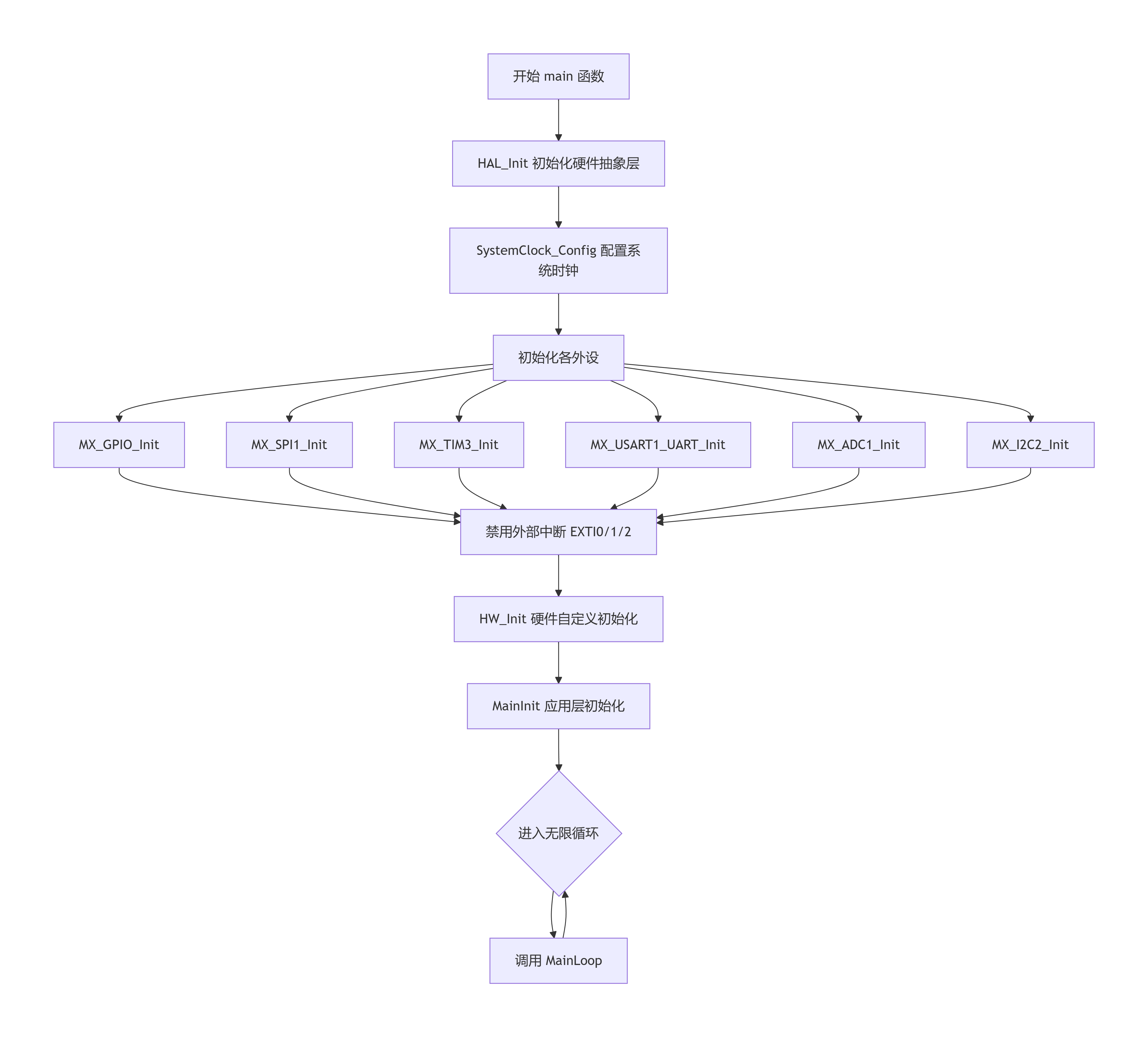
IRQ,SYNC0,SYNC1,和心跳定时器的中断需要由ethercat协议栈统一调度,所以在此之前需要保障这些中断是关闭的。
int main(void)
{
/* USER CODE BEGIN 1 */
/* USER CODE END 1 */
/* MCU Configuration--------------------------------------------------------*/
/* Reset of all peripherals, Initializes the Flash interface and the Systick. */
HAL_Init();
/* USER CODE BEGIN Init */
/* USER CODE END Init */
/* Configure the system clock */
SystemClock_Config();
/* USER CODE BEGIN SysInit */
/* USER CODE END SysInit */
/* Initialize all configured peripherals */
MX_GPIO_Init();
MX_SPI1_Init();
MX_TIM3_Init();
MX_USART1_UART_Init();
MX_ADC1_Init();
MX_I2C2_Init();
/* USER CODE BEGIN 2 */
HAL_NVIC_DisableIRQ(EXTI0_IRQn);
HAL_NVIC_DisableIRQ(EXTI1_IRQn);
HAL_NVIC_DisableIRQ(EXTI2_IRQn);
HW_Init();
MainInit();
/* USER CODE END 2 */
/* Infinite loop */
/* USER CODE BEGIN WHILE */
while (1)
{
/* USER CODE END WHILE */
/* USER CODE BEGIN 3 */
MainLoop();
}
/* USER CODE END 3 */
}
业务逻辑
/////////////////////////////////////////////////////////////////////////////////////////
/**
\param pData pointer to input process data
\brief This function will copies the inputs from the local memory to the ESC memory
to the hardware
*////////////////////////////////////////////////////////////////////////////////////////
void APPL_InputMapping(UINT16* pData)
{
pData[0] = KEY0x6000.KEY0;
pData[1] = KEY0x6000.KEY1;
}
/////////////////////////////////////////////////////////////////////////////////////////
/**
\param pData pointer to output process data
\brief This function will copies the outputs from the ESC memory to the local memory
to the hardware
*////////////////////////////////////////////////////////////////////////////////////////
void APPL_OutputMapping(UINT16* pData)
{
LED0x7000.LED0 = pData[0];
LED0x7000.LED1 = pData[1];
}
/////////////////////////////////////////////////////////////////////////////////////////
/**
\brief This function will called from the synchronisation ISR
or from the mainloop if no synchronisation is supported
*////////////////////////////////////////////////////////////////////////////////////////
void APPL_Application(void)
{
KEY0x6000.KEY0 = HAL_GPIO_ReadPin(INPUT0_GPIO_Port,INPUT0_Pin);
KEY0x6000.KEY1 = HAL_GPIO_ReadPin(INPUT1_GPIO_Port,INPUT1_Pin);
LED0x7000.LED0 ? HAL_GPIO_WritePin(LED0_GPIO_Port,LED0_Pin,GPIO_PIN_SET) : HAL_GPIO_WritePin(LED0_GPIO_Port,LED0_Pin,GPIO_PIN_RESET);
LED0x7000.LED1 ? HAL_GPIO_WritePin(LED1_GPIO_Port,LED1_Pin,GPIO_PIN_SET) : HAL_GPIO_WritePin(LED1_GPIO_Port,LED1_Pin,GPIO_PIN_RESET);
}
流程图
演示
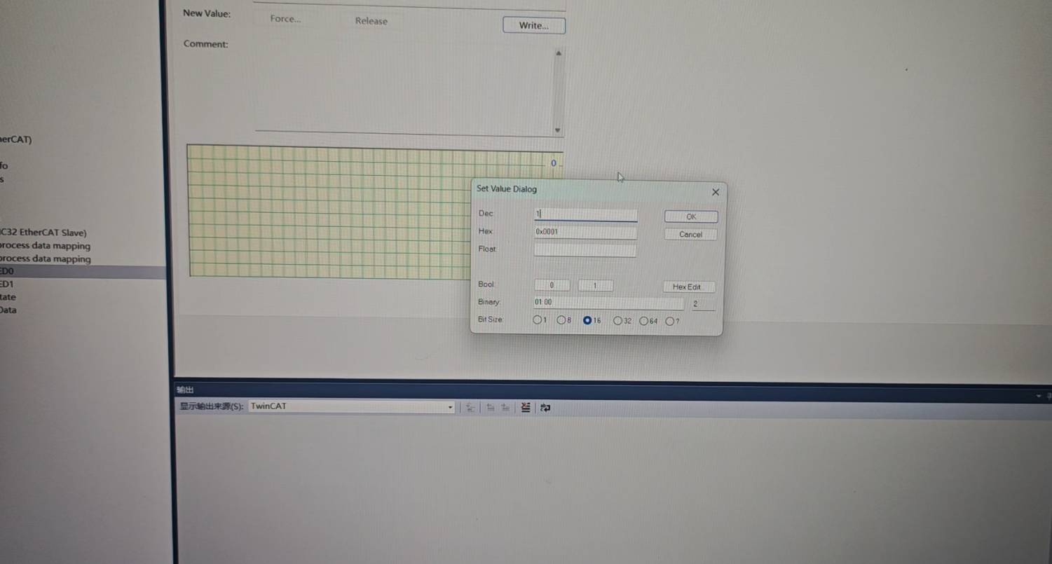
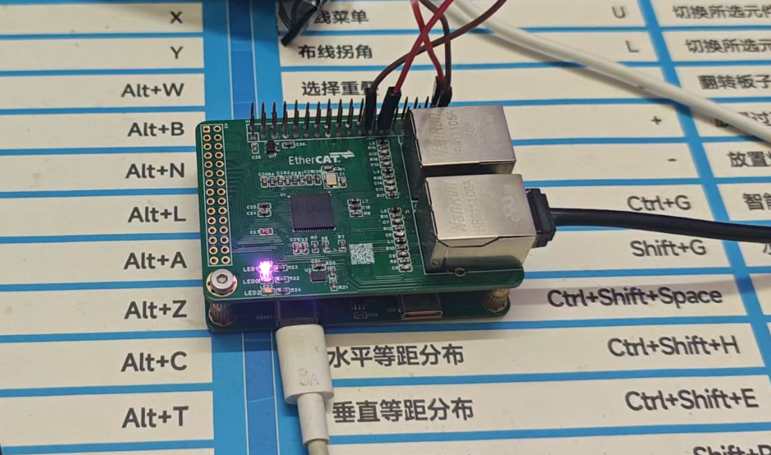
六,心得体会
- 硬件设计:
- 双板架构有效隔离了EtherCAT实时通信与应用处理,降低开发复杂度,主控板可单独调试,扩展板可复用于其他MCU平台。
- 高速信号(EtherCAT差分对、SPI、USB)必须严格遵守PCB设计规则:阻抗匹配、等长、包地、完整参考平面。
- 软件调试:
- SSC Tool生成的从站协议栈框架完善,但需根据实际硬件调整SPI读写函数和中断处理。
- 中断驱动方式(IRQ)比轮询更高效,能及时响应主站数据变化。
- SPI通信速率需匹配LAN9252时序,实测10MHz稳定,超过12MHz可能出错。
- IRQ,SYNC0,SYNC1,和心跳定时器的中断需要由ethercat协议栈统一调度,所以在此之前需要保障这些中断是关闭的。
- 六期活动主题的体现:
- 模块化设计:主控板和扩展板分离,符合“模块化”主题,便于功能剪裁和升级。
- 软硬协同:STM32G474的数学加速单元(CORDIC、FMAC)可为后续伺服驱动算法预留,契合“智能控制”主题。
本项目成功实现了基于STM32G474与LAN9252的EtherCAT从站IO控制器,采用双板架构,完成了2输入2输出的基本功能。移植SSC协议栈,掌握了EtherCAT从站开发全流程,为后续复杂工业控制产品奠定了基础。


 空耳-
空耳- 陌--空耳-