硬件和功能介绍
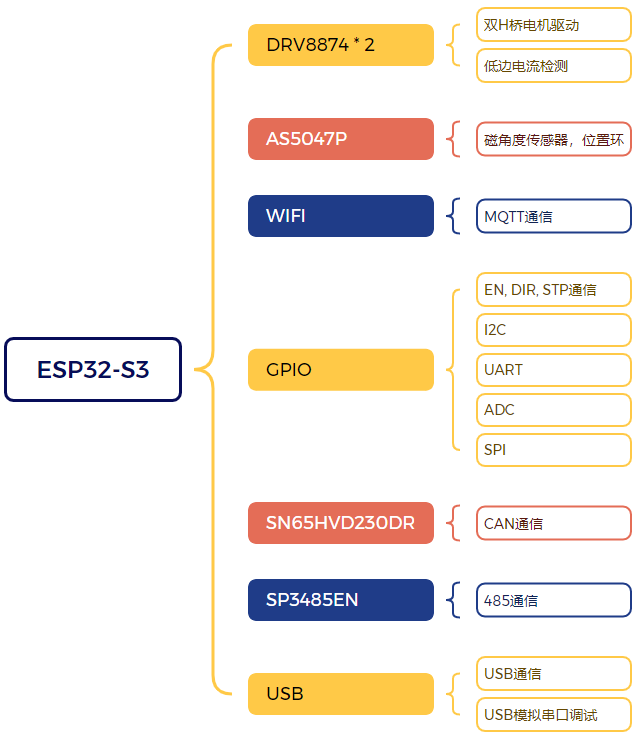
这是一款安装在42步进电机背面的FOC驱动器,与电机相同尺寸,支持电流环、速度环、位置环三环FOC控制,支持多种通讯接口,包括CAN,MODBUS,RS485,UART,I2C以及常见的EN、DIR、STP控制,以及基于WIF的MQTT。
我曾在一年前制作过一个FOC步进电机驱动,当时使用的驱动芯片是TI的DRV8962。后续使用中发现一系列问题。主要的几个问题如下:
1,DRV8962使用并不广泛,器件昂贵且难以购买。
2,DRV8962内置电流镜检测的是高端电流,但高端电流检测目前并没有受到大多数开源电机控制库的支持。
3,板载UART-USB接口虽然在调试阶段增加便利性,但是却让日后添加UART外设传感器变得非常不便。
4,5V稳压二极管虽然能对接口带来保护,但在RS485, CAN等差模信号遇到较高的共模干扰时,稳压二极管反而会造成通信异常。
因此在本次活动中我更换方案,重新设计了这款驱动器。
模块设计思路、选型及框图介绍
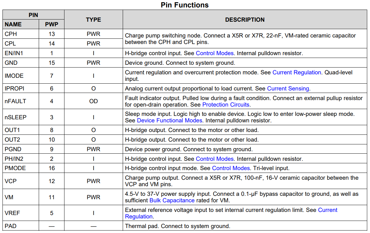
本项目使用的核心模块有两个,其中主控使用ESP32-S3,电机驱动使用的是两片DRV8874 H桥驱动器,支持6A电流驱动。
ESP32-S3-WROOM-1-N16R8: https://www.digikey.hk/zh/products/detail/espressif-systems/ESP32-S3-WROOM-1-N16R8/16162642
DRV8874: https://www.digikey.hk/zh/products/detail/texas-instruments/drv8874pwpr/11502339
DRV8874的集成度非常高,上面已经集成了低边电流测量功能,板载再加一个编码器识别电机角度即可。我选择的是AS5047P非接触式磁编码器。
其他的模块是为了一些通信和调试功能服务。
模块原理图、PCB简单介绍
先看一下原理图全貌,每个功能区域都单独用框框了起来。MCU引脚分配也都使用标签桥接单独列出,方便查询及修改。
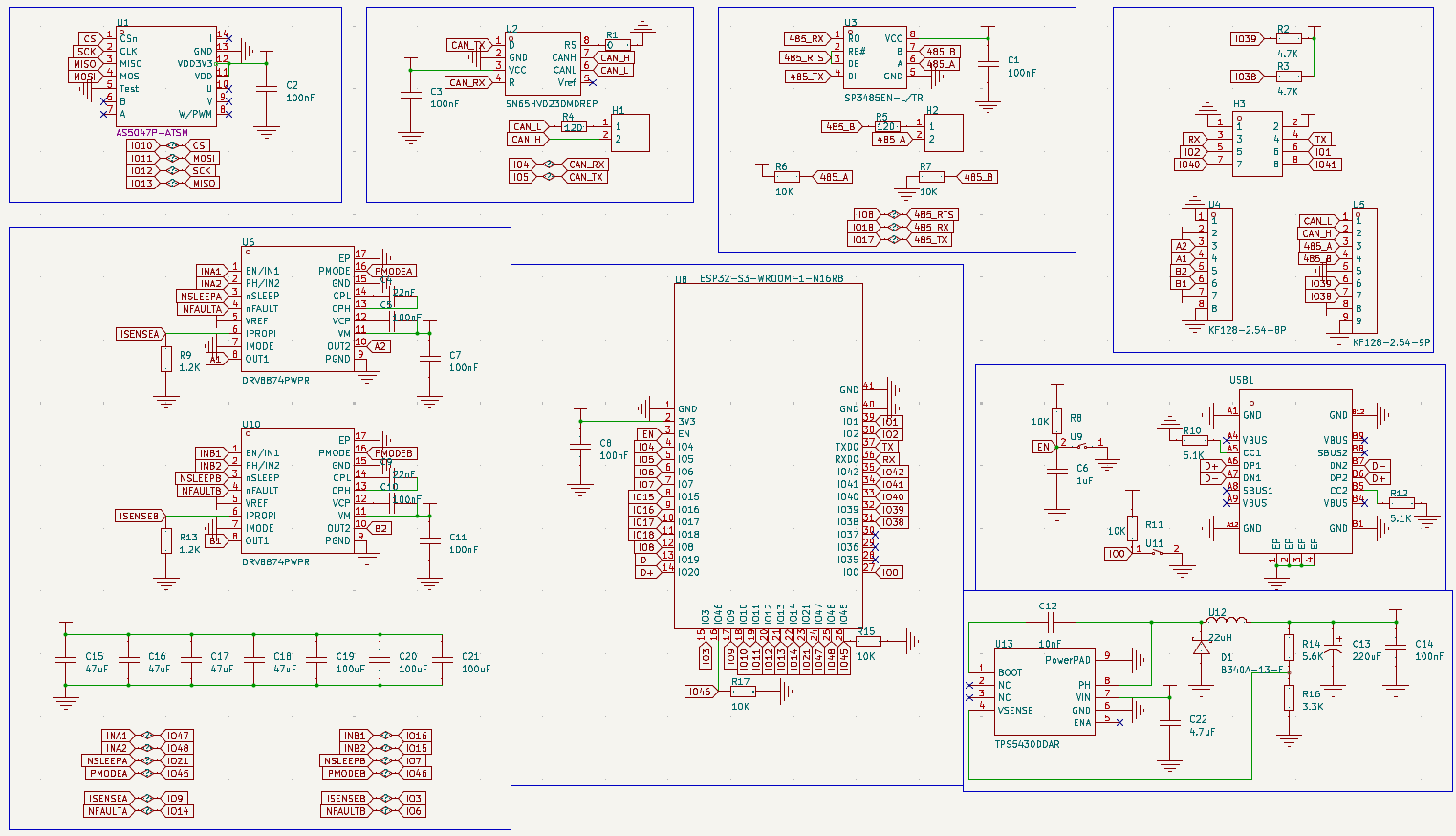
下面每一个部分讲一下设计需要特别注意的地方:
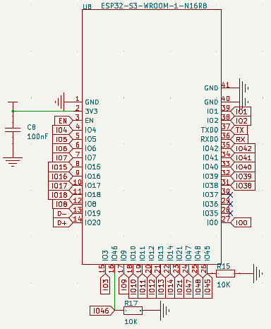
ESP32-S3-WROOM模块要特别注意strapping引脚的电平配置。虽然默认内置了弱上/下拉,但我实际使用中发现内置弱上/下拉力度太弱,非常容易被干扰导致启动或者刷血异常,因此还是最好通过外置电阻进行配置。同时,在使用这些strapping管脚时要特别注意,最好不要用做输入功能,以免被其他设备上电默认输出电平影响启动,另外在作为输出引脚使用时也要注意相关设备引脚的默认上/下拉配置。
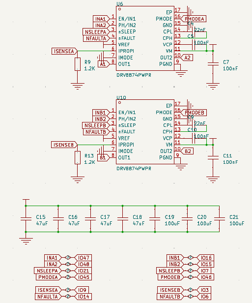
电机驱动模式尽可能不要用电阻配置死,而是直接连接单片机,靠单片机来进行配置。这里两个PMODE引脚使用了ESP32-S3上的strapping管脚,通过查询规格书可以看到这个管脚没有上下拉配置,可以放心使用。
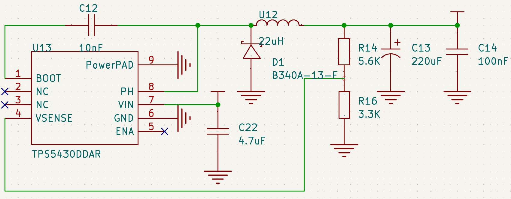
电源设计注意输出电容要选一个大容值的钽电容或者固态电容。不能直接用陶瓷电容,否则ESR不满足要求,需要修改反馈回路。其他原理图上没什么讲究,更多的讲就是在PCB Layout上。
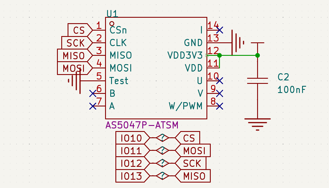
AS5047P使用SPI进行通信,效率比较高。连接ESP32-S3时尽量使用硬件VSPI,以获得最好的效果。
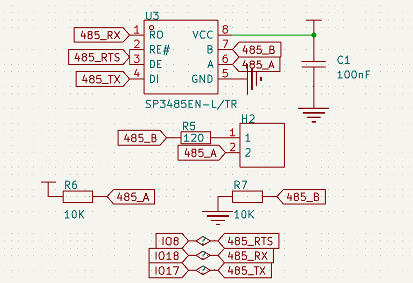
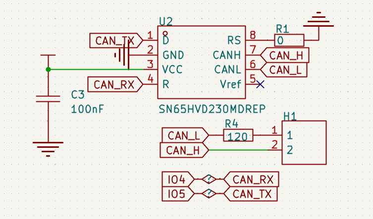
RS485和CAN通信部分添加了可选的终端电阻接入跳线帽,方便使用。
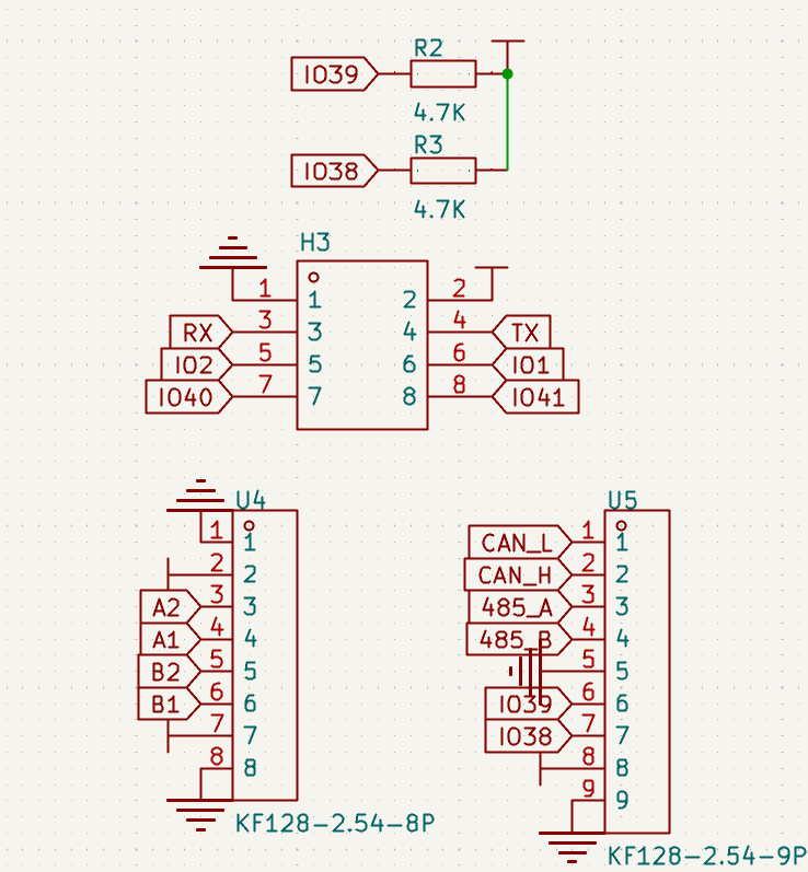
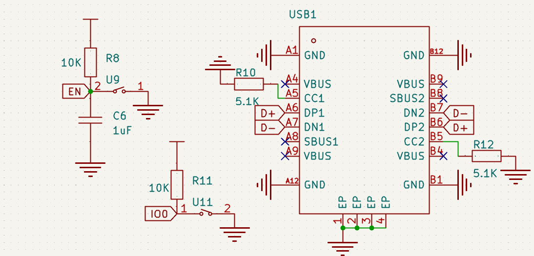
板子接口设计的比较多样化,调试和烧录固件可以试用USB或者UART,板载了RST和BOOT按钮可以方便快速进入烧写模式。另外使用2.54双排针引出GPIO,可以方便使用一些ADC, SPI, I2C, UART等传感器或者额外的执行部件例如继电器,LED等。主要的通信端口,电源端口和电机端口使用的KF128螺栓端子,工业领域较为常见且通用度高,非常灵活。
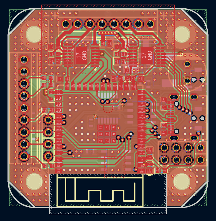
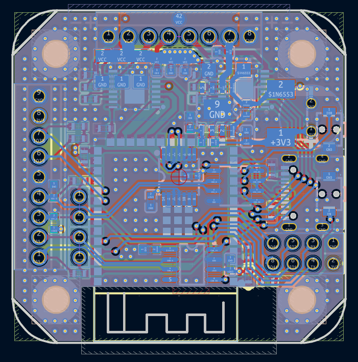
最后再看一下PCB,设计的比较小巧,又要满足部分线路的大电流和抗干扰,layout上讲究还是比较多的,大家直接看图,我就不过多赘述了。
调试软件介绍、关键代码片段及说明
由于485, CAN, MQTT等我在之前的文章中已经做过演示,这里就不再追溯了,感兴趣的可以看看我之前的项目:
https://www.eetree.cn/project/3519
这里主要是增加了电流环的配置,以及重写了硬件配置部分,让代码可读性更高。
#include <SimpleFOC.h>
#include <CanSerial.h>
#include <MQTTSerial.h>
// Driver
#define MODE_A_PIN 45
#define NSLEEP_A_PIN 21
#define NFAULT_A_PIN 14
#define ISENSE_A_PIN 9
#define IN1_A_PIN 47
#define IN2_A_PIN 48
#define MODE_B_PIN 46
#define NSLEEP_B_PIN 7
#define NFAULT_B_PIN 6
#define ISENSE_B_PIN 3
#define IN1_B_PIN 16
#define IN2_B_PIN 15
StepperMotor motor = StepperMotor(50);
StepperDriver4PWM driver = StepperDriver4PWM(IN1_A_PIN, IN2_A_PIN, IN1_B_PIN, IN2_B_PIN);
LowsideCurrentSense current_sense = LowsideCurrentSense(540, ISENSE_A_PIN, ISENSE_B_PIN);
// instantiate the sensor
#define SENSOR_CS_PIN 10
MagneticSensorSPI sensor = MagneticSensorSPI(AS5047_SPI, SENSOR_CS_PIN);
// instantiate the commander
Commander commander = Commander(Serial);
void onMotor(char *cmd) {
commander.motor(&motor, cmd);
}
// instantiate the step dir interface
#define STEP_PIN 39
#define DIR_PIN 40
StepDirListener step_dir = StepDirListener(STEP_PIN, DIR_PIN, _2PI / 200.0);
void onStep() {
step_dir.handle();
}
// instantiate the RS485 interface
#define RS485_RX_PIN 18
#define RS485_TX_PIN 17
#define RS485_RTS_PIN 8
#define RS485_BAUD 9600
#define RS485 Serial1
Commander commander_rs485 = Commander(RS485);
void onMotor_rs485(char *cmd) {
commander_rs485.motor(&motor, cmd);
}
// instantiate the CAN interface
#define CAN_RX_PIN 4
#define CAN_TX_PIN 5
#define CAN_SPEED 500
#define CAN_ID 'A'
CanSerial CAN;
Commander commander_can = Commander(CAN);
void onMotor_can(char *cmd) {
commander_can.motor(&motor, cmd);
}
// instantiate the MQTT interface
#define SSID ""
#define PASSWORD ""
#define MQTT_SERVER "192.168.x.x"
#define PORT 1883
#define MQTT_USR ""
#define MQTT_PWD ""
#define CLIENT_ID "stepper"
#define TOPIC_RX "stepper/rx"
#define TOPIC_TX "stepper/tx"
MQTTSerial MQTT;
Commander commander_mqtt = Commander(MQTT);
void onMotor_mqtt(char *cmd) {
commander_mqtt.motor(&motor, cmd);
}
void setup() {
// use monitoring with serial
Serial.begin(115200);
// while (!Serial)
// {
// delay(10);
// }
SimpleFOCDebug::enable(&Serial);
// motor.useMonitoring(Serial);
// driver config
pinMode(MODE_A_PIN, OUTPUT);
pinMode(NSLEEP_A_PIN, OUTPUT);
pinMode(NFAULT_A_PIN, INPUT_PULLUP);
pinMode(MODE_B_PIN, OUTPUT);
pinMode(NSLEEP_B_PIN, OUTPUT);
pinMode(NFAULT_B_PIN, INPUT_PULLUP);
bool mode = HIGH; //Low = PH/EN; High = PWM; Hi-Z = Independent Half-Bridge
digitalWrite(MODE_A_PIN, mode);
digitalWrite(MODE_B_PIN, mode);
bool nsleep = HIGH; //Low = sleep; High = enable device
digitalWrite(NSLEEP_A_PIN, nsleep);
digitalWrite(NSLEEP_B_PIN, nsleep);
driver.voltage_power_supply = 12;
if (!driver.init()) {
Serial.println("Driver init failed!");
}
motor.linkDriver(&driver);
// current sensor config
current_sense.linkDriver(&driver);
if (!current_sense.init()) {
Serial.println("Current sense init failed!");
}
motor.linkCurrentSense(¤t_sense);
// position sensor config
sensor.init();
motor.linkSensor(&sensor);
// motor config
motor.voltage_sensor_align = driver.voltage_power_supply * 0.8;
motor.torque_controller = TorqueControlType::voltage;
motor.controller = MotionControlType::velocity;
// motor.PID_velocity.P = 0.2;
// motor.PID_velocity.I = 20;
// motor.PID_velocity.D = 0.001;
// motor.PID_velocity.output_ramp = 1000;
// motor.LPF_velocity.Tf = 0.01;
// motor.P_angle.P = 20;
// motor.P_angle.I = 0;
// motor.P_angle.D = 0;
// motor.P_angle.output_ramp = 10000;
// motor.LPF_angle.Tf = 0;
// motor.motion_downsample = 100;
if (!motor.init()) {
Serial.println("Motor init failed!");
}
if (!motor.initFOC()) {
Serial.println("FOC init failed!");
}
// init serial interface
commander.add('M', onMotor, "full motor config");
// // init step and dir pins
// step_dir.init();
// step_dir.enableInterrupt(onStep);
// step_dir.attach(&motor.target);
// init RS485
RS485.begin(RS485_BAUD, SERIAL_8N1, RS485_RX_PIN, RS485_TX_PIN);
while (!RS485) {
delay(10);
}
if (!RS485.setPins(-1, -1, -1, RS485_RTS_PIN)) {
Serial.print("Failed to set RS485 pins");
}
if (!RS485.setMode(UART_MODE_RS485_HALF_DUPLEX)) {
Serial.print("Failed to set RS485 mode");
}
commander_rs485.add('M', onMotor_rs485, "full motor config");
// init CAN
if (!CAN.begin(CAN_RX_PIN, CAN_TX_PIN, CAN_SPEED, CAN_ID)) {
Serial.println("CAN bus failed!");
}
commander_can.add('M', onMotor_can, "full motor config");
// // init MQTT
// MQTT.begin(SSID, PASSWORD, MQTT_SERVER, PORT, MQTT_USR, MQTT_PWD, CLIENT_ID, TOPIC_RX, TOPIC_TX);
// commander_mqtt.add('M', onMotor_mqtt, "full motor config");
Serial.println("Setup Done!");
}
void loop() {
motor.loopFOC();
motor.move();
commander.run();
commander_rs485.run();
commander_can.run();
// MQTT.loop();
// commander_mqtt.run();
// motor.monitor();
}
模块调通的功能展示图

具体的功能演示,由于需要观察电机的动态情况,图片难以展示,大家可以直接参考视频中的内容。
心得体会
时隔一年再次参加电子森林的活动,活动依旧创意十足,诚意满满!

 小小洋洋
小小洋洋