所选任务
选择的是参照XIAO SAMD21重新设计一款MCU核心板,要求:
- 使用TQFP-48封装的器件替换掉原设计中的QFN-48封装的器件,器件的资源跟原设计一致,只有封装发生了变化
- 用到的MCU芯片需在DigiKey官网 上有货且正常售卖
- 核心板上的其它器件以及管脚连接与原设计完全一致
- 核心板的样式、尺寸跟原设计一致
- 考虑到TQFP-48封装的器件(9x9mm)相对于原设计中QFN-48封装的器件(7x7mm)占板面积稍大,自己设计的核心板可以将部分元器件放置在背后
模块设计思路及选型
根据任务要求,我选择了ATSAMD21G18A-AU这款TQFP-48的芯片,重新设计了Seeed Studio XIAO SAMD21。与原芯片相比,除封装外,所有外设资源相同,具有 14 个引脚,可用于 11 个数字接口、11 个模拟接口、10 个 PWM 接口(d1-d10)、1 个 DAC 输出引脚 D0、1 个 SWD 焊盘接口、1 个 I2C 接口、1 个 SPI 接口、1 个 UART 接口、串行通信指示灯(T/R)、通过引脚复用的闪烁灯(L)。LED 的颜色(电源、L、RX、TX)分别为绿色、黄色、蓝色和蓝色。此外,具有 Type-C 接口,可供电和下载代码。板上有两个复位按钮,可以短接它们来复位板子。
芯片的得捷链接:ATSAMD21G18A-AU
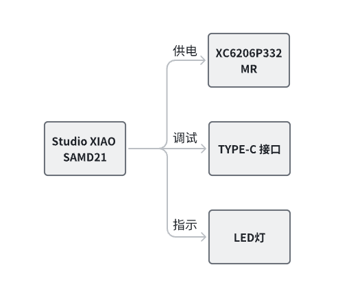
设计框图
原理图和PCB模块介绍
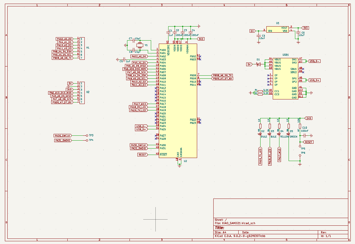
原理图
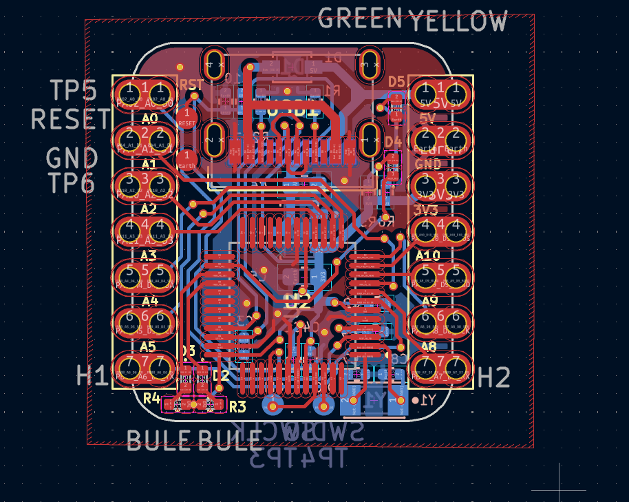
PCB
- 强大的 CPU:ARM® Cortex®-M0+ 32 位 48MHz 微控制器(SAMD21G18),具有 256KB Flash 和 32KB SRAM。
- 灵活的兼容性:兼容 Arduino IDE。
- 简单的项目操作:适合面包板使用。
- 小巧尺寸:拇指大小(21x17.8mm),适用于可穿戴设备和小型项目。
- 多种开发接口:11 个数字/模拟引脚、10 个 PWM 引脚、1 个 DAC 输出、1 个 SWD 焊盘接口、1 个 I2C 接口、1 个 UART 接口、1 个 SPI 接口。
模块主要性能指标和管脚定义
主要性能指标
项目 | 参数 |
|---|---|
CPU | ARM Cortex-M0+ CPU(SAMD21G18),最高运行频率 48MHz |
Flash 内存 | 256KB |
SRAM | 32KB |
数字 I/O 引脚 | 11 |
模拟 I/O 引脚 | 11 |
I2C 接口 | 1 |
SPI 接口 | 1 |
QTouch | 7 (A0,A1,A6,A7,A8,A9,A10) |
UART 接口 | 1 |
供电和下载接口 | Type-C |
电源 | 3.3V/5V DC |
尺寸 | 21×17.8×3.5mm |
关于通用 I/O 引脚: MCU 的工作电压为 3.3V。如果连接到通用 I/O 引脚的电压输入高于 3.3V,可能会导致芯片损坏。
关于电源引脚: 内置的 DC-DC 转换电路能够将 5V 电压转换为 3.3V,因此可以通过 5V-PIN 使用 5V 电源为设备供电。
管脚定义
脚属性 | 管脚名 | 管脚编号 | 管脚名 | 管脚属性 | |
I/O | PA02_A0_D0 | 1 | 14 | +5V | P |
I/O | PA4_A1_D1 | 2 | 13 | GND | P |
I/O | PA10_A2_D2 | 3 | 12 | 3V3 | P |
I/O | PA11_A3_D3 | 4 | 11 | PA6_A10_D10_MOSI | I/O |
I/O | PA8_A4_D4_SDA | 5 | 10 | PA5_A9_D9_MISO | I/O |
I/O | PA9_A5_D5_SCL | 6 | 9 | PA7_A8_D8_SCK | I/O |
I/O | PB08_A6_D6_TX | 7 | 8 | PB09_A7_D7_RX | I/O |
板上设置及标识
标记 | 名称 | 默认状态 | 描述 |
D5 | PWR | 亮 | 指示3.3V电压是否工作正常 |
D6 | L | 灭 | 通过编程可以进行状态指示 |
D2、D3 | 串行通信指示灯 | 灭 | 通过编程可以指示通信状态 |
调试过程
调试工具
使用PlatformIO,Arduino框架,硬件仅需一根usb线。
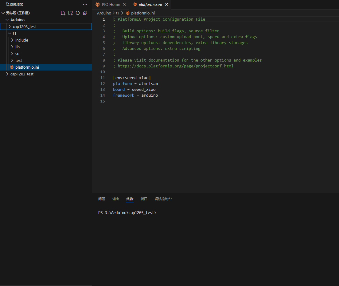
编程页面
数字输入和输出
- 使用引脚6作为数字引脚:
const int buttonPin = 6;     // the number of the pushbutton pin
const int ledPin =  13;      // the number of the LED pin

int buttonState = 0;         // variable for reading the pushbutton status

void setup() {
  // initialize the LED pin as an output:
  pinMode(ledPin, OUTPUT);
  // initialize the pushbutton pin as an input:
  pinMode(buttonPin, INPUT);
}

void loop() {
  // read the state of the pushbutton value:
  buttonState = digitalRead(buttonPin);

  // check if the pushbutton is pressed. If it is, the buttonState is HIGH:
  if (buttonState == HIGH) {
    // turn LED on:
    digitalWrite(ledPin, HIGH);
  } else {
    // turn LED off:
    digitalWrite(ledPin, LOW);
  }
}
模拟读取
- 使用引脚6作为模拟引脚:
void setup() {
  // declare the ledPin as an OUTPUT:
  pinMode(ledPin, OUTPUT);
}

void loop() {
  // read the value from the sensor:
  sensorValue = analogRead(sensorPin);
  // turn the ledPin on
  digitalWrite(ledPin, HIGH);
  // stop the program for <sensorValue> milliseconds:
  delay(sensorValue);
  // turn the ledPin off:
  digitalWrite(ledPin, LOW);
  // stop the program for for <sensorValue> milliseconds:
  delay(sensorValue);
}
串口
- 串口试验:
void setup() {
    Serial.begin(115200);
    while (!Serial);
}

void loop() {
    Serial.println("Hello,World");
    delay(1000);
}
DAC
- 使用13作为输出管脚,实现DAC功能
#define DAC_PIN 13 // Make code a bit more legible
float x = 0; // Value to take the sin of
float increment = 0.02;  // Value to increment x by each time
int frequency = 440; // Frequency of sine wave

void setup()
{
  analogWriteResolution(10); // Set analog out resolution to max, 10-bits
  analogReadResolution(12); // Set analog input resolution to max, 12-bits

  Serial.begin(9600);
}

void loop()
{
  // Generate a voltage value between 0 and 1023.
  // Let's scale a sin wave between those values:
  // Offset by 511.5, then multiply sin by 511.5.
  int dacVoltage = (int)(511.5 + 511.5 * sin(x));
  x += increment; // Increase value of x

  // Generate a voltage between 0 and 3.3V.
  // 0= 0V, 1023=3.3V, 512=1.65V, etc.
  analogWrite(DAC_PIN, dacVoltage);

  // Now read A1 (connected to A0), and convert that
  // 12-bit ADC value to a voltage between 0 and 3.3.
  float voltage = analogRead(A1) * 3.3 / 4096.0;
  Serial.println(voltage); // Print the voltage.
  delay(10); // Delay 10ms
}
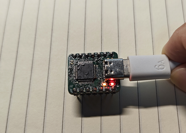
试验效果图
详细试验效果请观看视频
心得体会
这次我使用KiCAD设计了板子,既巩固了设计能力,又熟悉了KiCAD,还使用了PlatformIO,用于管理项目和使用Arduino框架十分方便。