
一、项目介绍
本项目使用恩智浦的FRDM-MCXA346开发板实现ADC数据采集功能,并在1.8寸TFT显示屏上显示ADC转换结果。
1.1硬件介绍
本项目使用以下硬件构成:
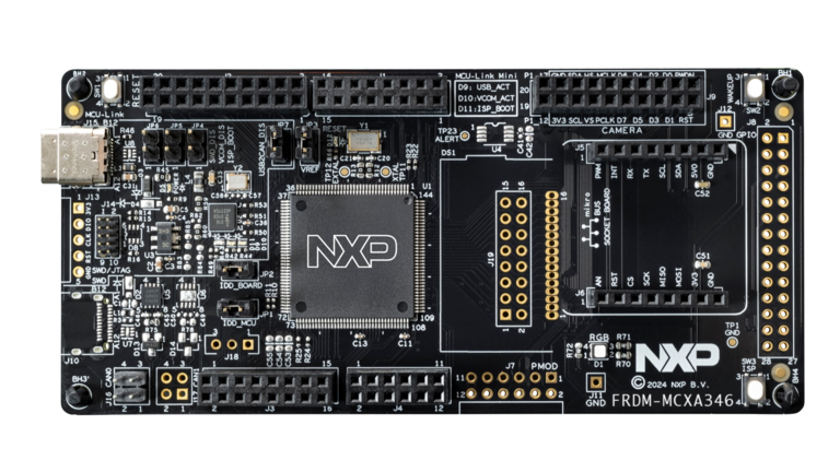
·FRDM-MCXA346
这是恩智浦公司推出的低成本Freedom 开发板,基于高性能 MCX A346 微控制器(Arm Cortex-M33)。 该开发板提供丰富的板载资源、完整的 Arduino 兼容引脚排列、OpenSDA 调试器,以及多种扩展接口, 是学习嵌入式开发、快速原型设计和产品验证的理想平台。
·可调电位器
这个电位器用来实现动态调整电压,改变ADC采集源。
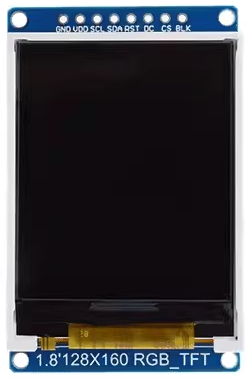
·TFT显示屏
本项目中使用的是1.8寸的TFT显示屏,SPI接口,分辨率为120*160,驱动核心是ST7735。用来动态显示ADC的转换结果。
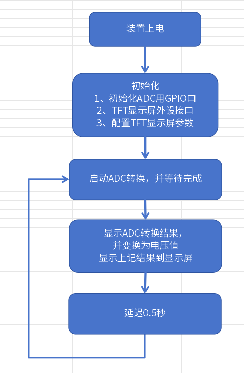
1.2功能概览
·装置上电
·初始化显示屏、ADC相关的GPIO口
·初始化ADC外设
·初始化显示屏的显示配置
·启动ADC采集转换处理并显示转换结果
1.2设计思路
实现功能预览的全部功能,实现步骤如下:
1)准备硬件和软件开发环境
2)连接电位器到主控板,电位器使用3.3V电压。
3)连接TFT显示屏到主控板FRDM-MCXA346。
4)编写代码,实现TFT显示屏正常显示;
二、功能实现
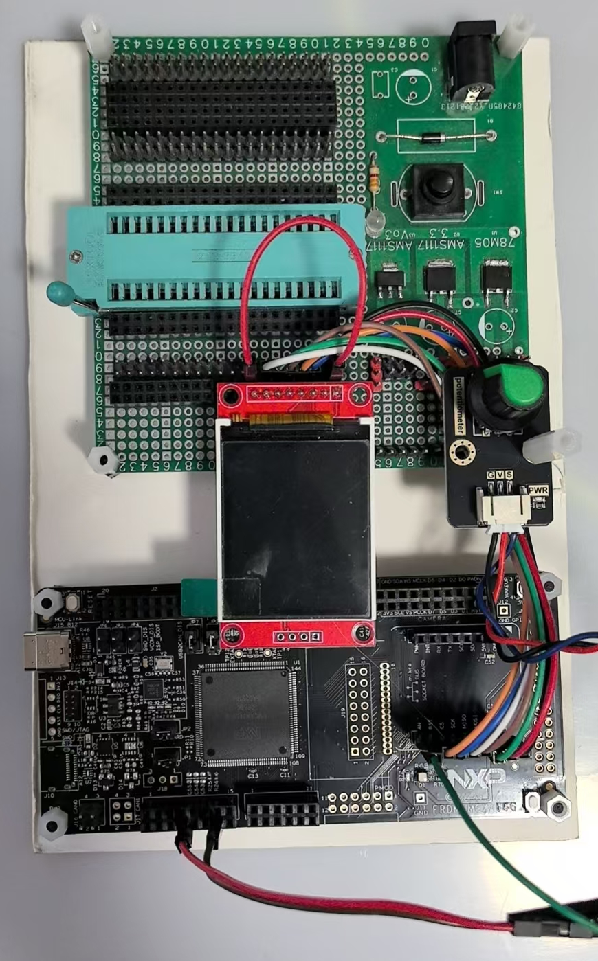
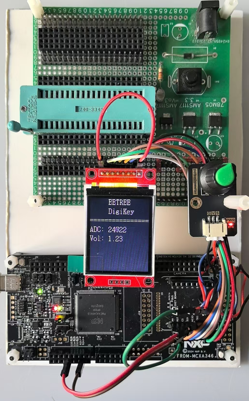
2.1 装置构成
实物拍摄
2.2软件流程图
2.3实现过程
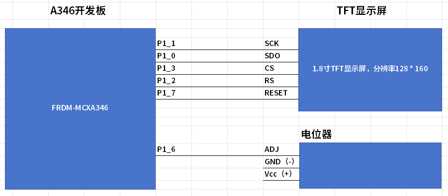
按照以下方式设置FRDM-MCXA346开发板、TFT显示屏之间、可调电阻
FRDM-MCXA346 TFT显示屏 可调电阻
============================================================
P1_6
P1_7 RESET
P1_3 CS
P1_1 SCK
P1_2 DC
P1_0 SDA
3V3 VCC
GND GND GND
3V3 LED Vcc
P1_6 可调端
===========================================================
各部分的关键代码:
2.3.1 GPIO初始化pin_mux.c
/* PORT2: Peripheral clock is enabled */
CLOCK_EnableClock(kCLOCK_GatePORT2);
/* LPUART2 peripheral is released from reset */
RESET_ReleasePeripheralReset(kLPUART2_RST_SHIFT_RSTn);
/* PORT2 peripheral is released from reset */
RESET_ReleasePeripheralReset(kPORT2_RST_SHIFT_RSTn);
/* ADC0 peripheral is released from reset */
RESET_ReleasePeripheralReset(kADC0_RST_SHIFT_RSTn);

// P1口和SPI有关的GPIO:P1_0, P1_1, P1_3, P1_6, P1_7
CLOCK_EnableClock(kCLOCK_GateGPIO1);
CLOCK_EnableClock(kCLOCK_GatePORT1);
RESET_ReleasePeripheralReset(kGPIO1_RST_SHIFT_RSTn);
RESET_ReleasePeripheralReset(kPORT1_RST_SHIFT_RSTn);

// 串口使用P2_35,P2_36
const port_pin_config_t port2_2_pin35_config = {/* Internal pull-up resistor is enabled */
.pullSelect = kPORT_PullUp,
/* Low internal pull resistor value is selected. */
.pullValueSelect = kPORT_LowPullResistor,
/* Fast slew rate is configured */
.slewRate = kPORT_FastSlewRate,
/* Passive input filter is disabled */
.passiveFilterEnable = kPORT_PassiveFilterDisable,
/* Open drain output is disabled */
.openDrainEnable = kPORT_OpenDrainDisable,
/* Low drive strength is configured */
.driveStrength = kPORT_LowDriveStrength,
/* Normal drive strength is configured */
.driveStrength1 = kPORT_NormalDriveStrength,
/* Pin is configured as LPUART2_TXD */
.mux = kPORT_MuxAlt3,
/* Digital input enabled */
.inputBuffer = kPORT_InputBufferEnable,
/* Digital input is not inverted */
.invertInput = kPORT_InputNormal,
/* Pin Control Register fields [15:0] are not locked */
.lockRegister = kPORT_UnlockRegister};
/* PORT2_2 (pin 35) is configured as LPUART2_TXD */
PORT_SetPinConfig(PORT2, 2U, &port2_2_pin35_config);

const port_pin_config_t port2_3_pin36_config = {/* Internal pull-up resistor is enabled */
.pullSelect = kPORT_PullUp,
/* Low internal pull resistor value is selected. */
.pullValueSelect = kPORT_LowPullResistor,
/* Fast slew rate is configured */
.slewRate = kPORT_FastSlewRate,
/* Passive input filter is disabled */
.passiveFilterEnable = kPORT_PassiveFilterDisable,
/* Open drain output is disabled */
.openDrainEnable = kPORT_OpenDrainDisable,
/* Low drive strength is configured */
.driveStrength = kPORT_LowDriveStrength,
/* Normal drive strength is configured */
.driveStrength1 = kPORT_NormalDriveStrength,
/* Pin is configured as LPUART2_RXD */
.mux = kPORT_MuxAlt3,
/* Digital input enabled */
.inputBuffer = kPORT_InputBufferEnable,
/* Digital input is not inverted */
.invertInput = kPORT_InputNormal,
/* Pin Control Register fields [15:0] are not locked */
.lockRegister = kPORT_UnlockRegister};
/* PORT2_3 (pin 36) is configured as LPUART2_RXD */
PORT_SetPinConfig(PORT2, 3U, &port2_3_pin36_config);


// TFT显示屏使用的SPI口用到的GPIO
//------------------------------------------------------------------------------------------------
gpio_pin_config_t output_config = {
.pinDirection = kGPIO_DigitalOutput,
.outputLogic = 0U
};
GPIO_PinInit(GPIO1, PIN_SDO, &output_config); // SDA
GPIO_PinInit(GPIO1, PIN_SCK, &output_config); // SCK
GPIO_PinInit(GPIO1, PIN_CS, &output_config); // CS
GPIO_PinInit(GPIO1, PIN_RS, &output_config); // DC
GPIO_PinInit(GPIO1, PIN_RST, &output_config); // RESET

const port_pin_config_t OUT = {/* Internal pull-up/down resistor is disabled */
.pullSelect = kPORT_PullDisable,
/* Low internal pull resistor value is selected. */
.pullValueSelect = kPORT_LowPullResistor,
/* Fast slew rate is configured */
.slewRate = kPORT_FastSlewRate,
/* Passive input filter is disabled */
.passiveFilterEnable = kPORT_PassiveFilterDisable,
/* Open drain output is disabled */
.openDrainEnable = kPORT_OpenDrainDisable,
/* Low drive strength is configured */
.driveStrength = kPORT_LowDriveStrength,
/* Normal drive strength is configured */
.driveStrength1 = kPORT_NormalDriveStrength,
/* Pin is configured as P3_18 */
.mux = kPORT_MuxAlt0,
/* Digital input enabled */
.inputBuffer = kPORT_InputBufferEnable,
/* Digital input is not inverted */
.invertInput = kPORT_InputNormal,
/* Pin Control Register fields [15:0] are not locked */
.lockRegister = kPORT_UnlockRegister};
// P1口和SPI有关的GPIO:P1_0,P1_1,P1_3
PORT_SetPinConfig(PORT1, PIN_SDO, &OUT);
PORT_SetPinConfig(PORT1, PIN_SCK, &OUT);
PORT_SetPinConfig(PORT1, PIN_CS, &OUT);
PORT_SetPinConfig(PORT1, PIN_RS, &OUT);
PORT_SetPinConfig(PORT1, PIN_RST, &OUT);
//-------------------------------------------------------------------------------------------------
ADC部分:
// ADC采集口P1_6 : ADC0_A22
const port_pin_config_t port1_6_config = {/* Internal pull-up/down resistor is disabled */
.pullSelect = kPORT_PullDisable,
/* Low internal pull resistor value is selected. */
.pullValueSelect = kPORT_LowPullResistor,
/* Fast slew rate is configured */
.slewRate = kPORT_FastSlewRate,
/* Passive input filter is disabled */
.passiveFilterEnable = kPORT_PassiveFilterDisable,
/* Open drain output is disabled */
.openDrainEnable = kPORT_OpenDrainDisable,
/* Low drive strength is configured */
.driveStrength = kPORT_LowDriveStrength,
/* Normal drive strength is configured */
.driveStrength1 = kPORT_NormalDriveStrength,
/* Pin is configured as ADC1_A8 */
.mux = kPORT_MuxAlt0,
/* Digital input disabled; it is required for analog functions */
.inputBuffer = kPORT_InputBufferDisable,
/* Digital input is not inverted */
.invertInput = kPORT_InputNormal,
/* Pin Control Register fields [15:0] are not locked */
.lockRegister = kPORT_UnlockRegister};
/* PORT1_10 (pin 3) is configured as ADC0_A22 */
PORT_SetPinConfig(PORT1, 6U, &port1_6_config);
2.3.2 TFT显示屏的处理代码(Lcd_Driver.c):
#include "pin_mux.h"
#include "board.h"

#include "font.h"
#include "Lcd_Driver.h"

extern void delay_ms(uint32_t ms);

extern volatile uint32_t g_systickCounter;

// 常用方向定义(根据你的接线方式调整)
#define ST7735_MADCTL_MY  0x80  // 行地址顺序
#define ST7735_MADCTL_MX  0x40  // 列地址顺序
#define ST7735_MADCTL_MV  0x20  // 行列交换
#define ST7735_MADCTL_ML  0x10  // 垂直刷新顺序
#define ST7735_MADCTL_RGB 0x00  // RGB顺序
#define ST7735_MADCTL_BGR 0x08  // BGR顺序
#define ST7735_MADCTL_MH  0x04  // 水平刷新顺序


// 当前显示方向
static st7735_rotation_t current_rotation = ST7735_ROTATION_0;

// 根据模块和接线定义方向表
// 常见的四种方向配置(可能需要根据具体模块调整)
static const st7735_orientation_t orientation_table[] = {
    // 0度
    {
        .madctl = ST7735_MADCTL_MX | ST7735_MADCTL_MY | ST7735_MADCTL_RGB,
        .width = SCREEN_WIDTH,
        .height = SCREEN_HEIGH,
        .x_start = 0,
        .y_start = 0
    },
    // 90度
    {
        .madctl = ST7735_MADCTL_MY | ST7735_MADCTL_MV | ST7735_MADCTL_RGB,
        .width = SCREEN_HEIGH,
        .height = SCREEN_WIDTH,
        .x_start = 0,
        .y_start = 0
    },
    // 180度
    {
        .madctl = ST7735_MADCTL_RGB,
        .width = SCREEN_WIDTH,
        .height = SCREEN_HEIGH,
        .x_start = 0,
        .y_start = 0
    },
    // 270度
    {
        .madctl = ST7735_MADCTL_MX | ST7735_MADCTL_MV | ST7735_MADCTL_RGB,
        .width = SCREEN_HEIGH,
        .height = SCREEN_WIDTH,
        .x_start = 0,
        .y_start = 0
    }
};


//液晶IO初始化配置
void LCD_GPIO_Init(void) {
LCD_CS_SET; // CS = 1;
LCD_RST_SET;    // RST = 1
LCD_RS_SET; // DC = 1
LCD_SCK_CLR; // SCK = 0
LCD_SDO_CLR; // SDO = 0
}

//向SPI总线传输一个8位数据
void SPI_WriteData(uint8_t Data) {
for (int counter = 0; counter < 8; counter++) {
LCD_SCK_CLR;
if ((Data & 0x80) == 0) {
LCD_SDO_CLR;
} else
LCD_SDO_SET;
Data = Data << 1;
LCD_SCK_SET;
}

LCD_SCK_CLR;

}

//向液晶屏写一个8位指令
void Lcd_WriteCmd(uint8_t Index) {
//SPI 写命令时序开始
LCD_CS_CLR;
LCD_RS_CLR;
SPI_WriteData(Index);
LCD_CS_SET;
}

//向液晶屏写一个8位数据
void Lcd_WriteData(uint8_t Data) {
LCD_CS_CLR;
LCD_RS_SET;
SPI_WriteData(Data);
LCD_CS_SET;
}
//向液晶屏写一个16位数据
void LCD_WriteData_16Bit(uint16_t Data) {
LCD_CS_CLR;
LCD_RS_SET;
SPI_WriteData(Data >> 8); //写入高8位数据
SPI_WriteData(Data); //写入低8位数据
LCD_CS_SET;
}

void Lcd_WriteReg(uint8_t Index, uint8_t Data) {
Lcd_WriteCmd(Index);
Lcd_WriteData(Data);
}

void Lcd_Reset(void) {
LCD_RST_CLR;
delay_ms(100);
LCD_RST_SET;
delay_ms(100);
}

//LCD Init For 1.44Inch LCD Panel with ST7735R.
void Lcd_Init(void) {
LCD_GPIO_Init();
Lcd_Reset(); //Reset before LCD Init.

//LCD Init For 1.44Inch LCD Panel with ST7735R.
Lcd_WriteCmd(0x11); //Sleep exit
delay_ms(200);

Lcd_WriteCmd(0xB1);
Lcd_WriteData(0x01);
Lcd_WriteData(0x2C);
Lcd_WriteData(0x2D);

Lcd_WriteCmd(0xB2);
Lcd_WriteData(0x01);
Lcd_WriteData(0x2C);
Lcd_WriteData(0x2D);

Lcd_WriteCmd(0xB3);
Lcd_WriteData(0x01);
Lcd_WriteData(0x2C);
Lcd_WriteData(0x2D);
Lcd_WriteData(0x01);
Lcd_WriteData(0x2C);
Lcd_WriteData(0x2D);

Lcd_WriteCmd(0xB4); //Column inversion
Lcd_WriteData(0x07);

//ST7735R Power Sequence
Lcd_WriteCmd(0xC0);
Lcd_WriteData(0xA2);
Lcd_WriteData(0x02);
Lcd_WriteData(0x84);
Lcd_WriteCmd(0xC1);
Lcd_WriteData(0xC5);

Lcd_WriteCmd(0xC2);
Lcd_WriteData(0x0A);
Lcd_WriteData(0x00);

Lcd_WriteCmd(0xC3);
Lcd_WriteData(0x8A);
Lcd_WriteData(0x2A);
Lcd_WriteCmd(0xC4);
Lcd_WriteData(0x8A);
Lcd_WriteData(0xEE);

Lcd_WriteCmd(0xC5); //VCOM
Lcd_WriteData(0x0E);

Lcd_WriteCmd(0x36); //MX, MY, RGB mode
Lcd_WriteData(0xC0);

//ST7735R Gamma Sequence
Lcd_WriteCmd(0xe0);
Lcd_WriteData(0x0f);
Lcd_WriteData(0x1a);
Lcd_WriteData(0x0f);
Lcd_WriteData(0x18);
Lcd_WriteData(0x2f);
Lcd_WriteData(0x28);
Lcd_WriteData(0x20);
Lcd_WriteData(0x22);
Lcd_WriteData(0x1f);
Lcd_WriteData(0x1b);
Lcd_WriteData(0x23);
Lcd_WriteData(0x37);
Lcd_WriteData(0x00);
Lcd_WriteData(0x07);
Lcd_WriteData(0x02);
Lcd_WriteData(0x10);

Lcd_WriteCmd(0xe1);
Lcd_WriteData(0x0f);
Lcd_WriteData(0x1b);
Lcd_WriteData(0x0f);
Lcd_WriteData(0x17);
Lcd_WriteData(0x33);
Lcd_WriteData(0x2c);
Lcd_WriteData(0x29);
Lcd_WriteData(0x2e);
Lcd_WriteData(0x30);
Lcd_WriteData(0x30);
Lcd_WriteData(0x39);
Lcd_WriteData(0x3f);
Lcd_WriteData(0x00);
Lcd_WriteData(0x07);
Lcd_WriteData(0x03);
Lcd_WriteData(0x10);

Lcd_WriteCmd(0x2a);
Lcd_WriteData(0x00);
Lcd_WriteData(0x00);
Lcd_WriteData(0x00);
Lcd_WriteData(0x7f);

Lcd_WriteCmd(0x2b);
Lcd_WriteData(0x00);
Lcd_WriteData(0x00);
Lcd_WriteData(0x00);
Lcd_WriteData(0x9f);

Lcd_WriteCmd(0xF0); //Enable test command
Lcd_WriteData(0x01);
Lcd_WriteCmd(0xF6); //Disable ram power save mode
Lcd_WriteData(0x00);

Lcd_WriteCmd(0x3A); //65k mode
Lcd_WriteData(0x05);

//ST7735R Frame Rate
Set_Rotation(ST7735_ROTATION_180);

Lcd_WriteCmd(0x29); //Display on

//    LCD_LED_CLR;
}

/*************************************************
 函数名:LCD_Set_Region
 功能:设置lcd显示区域,在此区域写点数据自动换行
 入口参数:xy起点和终点
 返回值:无
 *************************************************/
void Lcd_SetRegion(uint16_t x_start, uint16_t y_start, uint16_t x_end,
uint16_t y_end) {
Lcd_WriteCmd(0x2a);
Lcd_WriteData(0x00);
Lcd_WriteData(x_start); //Lcd_WriteData(x_start+2);
Lcd_WriteData(0x00);
Lcd_WriteData(x_end + 2);

Lcd_WriteCmd(0x2b);
Lcd_WriteData(0x00);
Lcd_WriteData(y_start + 0);
Lcd_WriteData(0x00);
Lcd_WriteData(y_end + 1);

Lcd_WriteCmd(0x2c);

}

/*************************************************
 函数名:LCD_Set_XY
 功能:设置lcd显示起始点
 入口参数:xy坐标
 返回值:无
 *************************************************/
void Lcd_SetXY(uint16_t x, uint16_t y) {
Lcd_SetRegion(x, y, x, y);
}

/*************************************************
 函数名:LCD_DrawPoint
 功能:画一个点
 入口参数:无
 返回值:无
 *************************************************/
void Gui_DrawPoint(uint16_t x, uint16_t y, uint16_t Data) {
Lcd_SetRegion(x, y, x + 1, y + 1);
LCD_WriteData_16Bit(Data);

}

/*****************************************
 函数功能:读TFT某一点的颜色
 出口参数:color  点颜色值
 ******************************************/
unsigned int Lcd_ReadPoint(uint16_t x, uint16_t y) {
unsigned int Data;
Lcd_SetXY(x, y);

//Lcd_ReadData();//丢掉无用字节
//Data=Lcd_ReadData();
Lcd_WriteData(Data);
return Data;
}
/*************************************************
 函数名:Lcd_Clear
 功能:全屏清屏函数
 入口参数:填充颜色COLOR
 返回值:无
 *************************************************/
void Lcd_Clear(uint16_t Color) {
unsigned int i, m;
Lcd_SetRegion(0, 0, SCREEN_WIDTH - 1, SCREEN_HEIGH - 1);
Lcd_WriteCmd(0x2C);
for (i = 0; i < SCREEN_WIDTH; i++)
for (m = 0; m < SCREEN_HEIGH; m++) {
LCD_WriteData_16Bit(Color);
}
}

void Gui_Circle(uint16_t X, uint16_t Y, uint16_t R, uint16_t fc) { //Bresenham算法
unsigned short a, b;
int c;
a = 0;
b = R;
c = 3 - 2 * R;
while (a < b) {
Gui_DrawPoint(X + a, Y + b, fc);     //        7
Gui_DrawPoint(X - a, Y + b, fc);     //        6
Gui_DrawPoint(X + a, Y - b, fc);     //        2
Gui_DrawPoint(X - a, Y - b, fc);     //        3
Gui_DrawPoint(X + b, Y + a, fc);     //        8
Gui_DrawPoint(X - b, Y + a, fc);     //        5
Gui_DrawPoint(X + b, Y - a, fc);     //        1
Gui_DrawPoint(X - b, Y - a, fc);     //        4

if (c < 0)
c = c + 4 * a + 6;
else {
c = c + 4 * (a - b) + 10;
b -= 1;
}
a += 1;
}
if (a == b) {
Gui_DrawPoint(X + a, Y + b, fc);
Gui_DrawPoint(X + a, Y + b, fc);
Gui_DrawPoint(X + a, Y - b, fc);
Gui_DrawPoint(X - a, Y - b, fc);
Gui_DrawPoint(X + b, Y + a, fc);
Gui_DrawPoint(X - b, Y + a, fc);
Gui_DrawPoint(X + b, Y - a, fc);
Gui_DrawPoint(X - b, Y - a, fc);
}

}
//画线函数,使用Bresenham 画线算法
void Gui_DrawLine(uint16_t x0, uint16_t y0, uint16_t x1, uint16_t y1,
uint16_t Color) {
int dx,             // difference in x's
dy,             // difference in y's
dx2,            // dx,dy * 2
dy2, x_inc,          // amount in pixel space to move during drawing
y_inc,          // amount in pixel space to move during drawing
error,         // the discriminant i.e. error i.e. decision variable
index;          // used for looping

Lcd_SetXY(x0, y0);
dx = x1 - x0;          //计算x距离
dy = y1 - y0;          //计算y距离

if (dx >= 0) {
x_inc = 1;
} else {
x_inc = -1;
dx = -dx;
}

if (dy >= 0) {
y_inc = 1;
} else {
y_inc = -1;
dy = -dy;
}

dx2 = dx << 1;
dy2 = dy << 1;

if (dx > dy)          //x距离大于y距离,那么每个x轴上只有一个点,每个y轴上有若干个点
{          //且线的点数等于x距离,以x轴递增画点
   // initialize error term
error = dy2 - dx;

// draw the line
for (index = 0; index <= dx; index++) //要画的点数不会超过x距离
{
//画点
Gui_DrawPoint(x0, y0, Color);

// test if error has overflowed
if (error >= 0) //是否需要增加y坐标值
{
error -= dx2;

// move to next line
y0 += y_inc; //增加y坐标值
} // end if error overflowed

// adjust the error term
error += dy2;

// move to the next pixel
x0 += x_inc; //x坐标值每次画点后都递增1
} // end for
} // end if |slope| <= 1
else //y轴大于x轴,则每个y轴上只有一个点,x轴若干个点
{ //以y轴为递增画点
  // initialize error term
error = dx2 - dy;

// draw the line
for (index = 0; index <= dy; index++) {
// set the pixel
Gui_DrawPoint(x0, y0, Color);

// test if error overflowed
if (error >= 0) {
error -= dy2;

// move to next line
x0 += x_inc;
} // end if error overflowed

// adjust the error term
error += dx2;

// move to the next pixel
y0 += y_inc;
} // end for
} // end else |slope| > 1
}

void Gui_box(uint16_t x, uint16_t y, uint16_t w, uint16_t h, uint16_t bc) {
Gui_DrawLine(x, y, x + w, y, 0xEF7D);
Gui_DrawLine(x + w - 1, y + 1, x + w - 1, y + 1 + h, 0x2965);
Gui_DrawLine(x, y + h, x + w, y + h, 0x2965);
Gui_DrawLine(x, y, x, y + h, 0xEF7D);
Gui_DrawLine(x + 1, y + 1, x + 1 + w - 2, y + 1 + h - 2, bc);
}
void Gui_box2(uint16_t x, uint16_t y, uint16_t w, uint16_t h, uint8_t mode) {
if (mode == 0) {
Gui_DrawLine(x, y, x + w, y, 0xEF7D);
Gui_DrawLine(x + w - 1, y + 1, x + w - 1, y + 1 + h, 0x2965);
Gui_DrawLine(x, y + h, x + w, y + h, 0x2965);
Gui_DrawLine(x, y, x, y + h, 0xEF7D);
}
if (mode == 1) {
Gui_DrawLine(x, y, x + w, y, 0x2965);
Gui_DrawLine(x + w - 1, y + 1, x + w - 1, y + 1 + h, 0xEF7D);
Gui_DrawLine(x, y + h, x + w, y + h, 0xEF7D);
Gui_DrawLine(x, y, x, y + h, 0x2965);
}
if (mode == 2) {
Gui_DrawLine(x, y, x + w, y, 0xffff);
Gui_DrawLine(x + w - 1, y + 1, x + w - 1, y + 1 + h, 0xffff);
Gui_DrawLine(x, y + h, x + w, y + h, 0xffff);
Gui_DrawLine(x, y, x, y + h, 0xffff);
}
}

/**************************************************************************************
 功能描述: 在屏幕显示一凸起的按钮框
 输   入: uint16_t x1,y1,x2,y2 按钮框左上角和右下角坐标
 输   出: 无
 **************************************************************************************/
void DisplayButtonDown(uint16_t x1, uint16_t y1, uint16_t x2, uint16_t y2) {
Gui_DrawLine(x1, y1, x2, y1, GRAY2);  //H
Gui_DrawLine(x1 + 1, y1 + 1, x2, y1 + 1, GRAY1);  //H
Gui_DrawLine(x1, y1, x1, y2, GRAY2);  //V
Gui_DrawLine(x1 + 1, y1 + 1, x1 + 1, y2, GRAY1);  //V
Gui_DrawLine(x1, y2, x2, y2, WHITE);  //H
Gui_DrawLine(x2, y1, x2, y2, WHITE);  //V
}

/**************************************************************************************
 功能描述: 在屏幕显示一凹下的按钮框
 输   入: uint16_t x1,y1,x2,y2 按钮框左上角和右下角坐标
 输   出: 无
 **************************************************************************************/
void DisplayButtonUp(uint16_t x1, uint16_t y1, uint16_t x2, uint16_t y2) {
Gui_DrawLine(x1, y1, x2, y1, WHITE); //H
Gui_DrawLine(x1, y1, x1, y2, WHITE); //V

Gui_DrawLine(x1 + 1, y2 - 1, x2, y2 - 1, GRAY1);  //H
Gui_DrawLine(x1, y2, x2, y2, GRAY2);  //H
Gui_DrawLine(x2 - 1, y1 + 1, x2 - 1, y2, GRAY1);  //V
Gui_DrawLine(x2, y1, x2, y2, GRAY2); //V
}

void Gui_DrawFont_GBK16(uint16_t x, uint16_t y, uint16_t fc, uint16_t bc,
uint8_t *s) {
unsigned char i, j;
unsigned short k, x0;
x0 = x;

while (*s) {
if ((*s) < 128) {
k = *s;
if (k == 13) {
x = x0;
y += 16;
} else {
if (k > 32)
k -= 32;
else
k = 0;

for (i = 0; i < 16; i++)
for (j = 0; j < 8; j++) {
if (asc16[k * 16 + i] & (0x80 >> j))
Gui_DrawPoint(x + j, y + i, fc);
else {
if (fc != bc)
Gui_DrawPoint(x + j, y + i, bc);
}
}
x += 8;
}
s++;
}

else {

for (k = 0; k < hz16_num; k++) {
if ((hz16[k].Index[0] == *(s))
&& (hz16[k].Index[1] == *(s + 1))) {
for (i = 0; i < 16; i++) {
for (j = 0; j < 8; j++) {
if (hz16[k].Msk[i * 2] & (0x80 >> j))
Gui_DrawPoint(x + j, y + i, fc);
else {
if (fc != bc)
Gui_DrawPoint(x + j, y + i, bc);
}
}
for (j = 0; j < 8; j++) {
if (hz16[k].Msk[i * 2 + 1] & (0x80 >> j))
Gui_DrawPoint(x + j + 8, y + i, fc);
else {
if (fc != bc)
Gui_DrawPoint(x + j + 8, y + i, bc);
}
}
}
}
}
s += 2;
x += 16;
}

}
}

void Gui_DrawFont_GBK24(uint16_t x, uint16_t y, uint16_t fc, uint16_t bc,
uint8_t *s) {
unsigned char i, j;
unsigned short k;

while (*s) {
if (*s < 0x80) {
k = *s;
if (k > 32)
k -= 32;
else
k = 0;

for (i = 0; i < 16; i++)
for (j = 0; j < 8; j++) {
if (asc16[k * 16 + i] & (0x80 >> j))
Gui_DrawPoint(x + j, y + i, fc);
else {
if (fc != bc)
Gui_DrawPoint(x + j, y + i, bc);
}
}
s++;
x += 8;
} else {

for (k = 0; k < hz24_num; k++) {
if ((hz24[k].Index[0] == *(s))
&& (hz24[k].Index[1] == *(s + 1))) {
for (i = 0; i < 24; i++) {
for (j = 0; j < 8; j++) {
if (hz24[k].Msk[i * 3] & (0x80 >> j))
Gui_DrawPoint(x + j, y + i, fc);
else {
if (fc != bc)
Gui_DrawPoint(x + j, y + i, bc);
}
}
for (j = 0; j < 8; j++) {
if (hz24[k].Msk[i * 3 + 1] & (0x80 >> j))
Gui_DrawPoint(x + j + 8, y + i, fc);
else {
if (fc != bc)
Gui_DrawPoint(x + j + 8, y + i, bc);
}
}
for (j = 0; j < 8; j++) {
if (hz24[k].Msk[i * 3 + 2] & (0x80 >> j))
Gui_DrawPoint(x + j + 16, y + i, fc);
else {
if (fc != bc)
Gui_DrawPoint(x + j + 16, y + i, bc);
}
}
}
}
}
s += 2;
x += 24;
}
}
}
void Gui_DrawFont_Num32(uint16_t x, uint16_t y, uint16_t fc, uint16_t bc,
uint16_t num) {
unsigned char i, j, k, c;
//lcd_text_any(x+94+i*42,y+34,32,32,0x7E8,0x0,sz32,knum[i]);
// w=w/8;

for (i = 0; i < 32; i++) {
for (j = 0; j < 4; j++) {
c = *(sz32 + num * 32 * 4 + i * 4 + j);
for (k = 0; k < 8; k++) {

if (c & (0x80 >> k))
Gui_DrawPoint(x + j * 8 + k, y + i, fc);
else {
if (fc != bc)
Gui_DrawPoint(x + j * 8 + k, y + i, bc);
}
}
}
}
}

// 行号
uint32_t lineno = 0;
uint8_t rows[10][16];
void lcd_println(uint8_t *str) {
uint8_t i = 0;
Gui_DrawFont_GBK16(0, 16 * lineno, WHITE, BLACK, str);
lineno = (lineno + 1) % 10;
Gui_DrawFont_GBK16(0, 16 * lineno, WHITE, BLACK, "                ");
}

void lcd_print(uint8_t *str) {
uint8_t i = 0;
Gui_DrawFont_GBK16(0, 16 * lineno, WHITE, BLACK, str);
}


// 如果你的模块需要偏移(某些模块有偏移量)
static const st7735_orientation_t orientation_table_with_offset[] = {
    // 0度
    {
        .madctl = ST7735_MADCTL_MX | ST7735_MADCTL_MY | ST7735_MADCTL_RGB,
        .width = SCREEN_WIDTH,
        .height = SCREEN_HEIGH,
        .x_start = 0,    // 可能需要调整为 0, 40 等
        .y_start = 0
    },
    // 90度
    {
        .madctl = ST7735_MADCTL_MY | ST7735_MADCTL_MV | ST7735_MADCTL_RGB,
        .width = SCREEN_HEIGH,
        .height = SCREEN_WIDTH,
        .x_start = 0,
        .y_start = 0     // 可能需要调整为 40
    },
    // 180度
    {
        .madctl = ST7735_MADCTL_RGB,
        .width = SCREEN_WIDTH,
        .height = SCREEN_HEIGH,
        .x_start = 0,
        .y_start = 0
    },
    // 270度
    {
        .madctl = ST7735_MADCTL_MX | ST7735_MADCTL_MV | ST7735_MADCTL_RGB,
        .width = SCREEN_HEIGH,
        .height = SCREEN_WIDTH,
        .x_start = 0,
        .y_start = 0
    }
};

/**
 * @brief 设置显示方向
 * @param rotation 方向:0, 90, 180, 270度
 */
void Set_Rotation(st7735_rotation_t rotation) {
    if (rotation > 3) {
        rotation = 0;
    }

    current_rotation = rotation;

    // 获取当前方向配置
    const st7735_orientation_t *orient = &orientation_table[rotation];

    // 设置MADCTL寄存器
    Lcd_WriteCmd(0x36);  // MADCTL命令
    Lcd_WriteData(orient->madctl);

    // 设置列地址(CASET)
    Lcd_WriteCmd(0x2A);  // CASET命令
    uint8_t caset_data[4] = {
        (orient->x_start >> 8) & 0xFF,
        orient->x_start & 0xFF,
        ((orient->x_start + orient->width - 1) >> 8) & 0xFF,
        (orient->x_start + orient->width - 1) & 0xFF
    };
    Lcd_WriteData(caset_data[0]);
    Lcd_WriteData(caset_data[1]);
    Lcd_WriteData(caset_data[2]);
    Lcd_WriteData(caset_data[3]);

    // 设置行地址(RASET)
    Lcd_WriteCmd(0x2B);  // RASET命令
    uint8_t raset_data[4] = {
        (orient->y_start >> 8) & 0xFF,
        orient->y_start & 0xFF,
        ((orient->y_start + orient->height - 1) >> 8) & 0xFF,
        (orient->y_start + orient->height - 1) & 0xFF
    };
    Lcd_WriteData(raset_data[0]);
    Lcd_WriteData(raset_data[1]);
    Lcd_WriteData(raset_data[2]);
    Lcd_WriteData(raset_data[3]);

}

/**
 * @brief 获取当前宽度
 */
uint16_t Get_Width(void) {
    return orientation_table[current_rotation].width;
}

/**
 * @brief 获取当前高度
 */
uint16_t Get_Height(void){
    return orientation_table[current_rotation].height;
}

/**
 * @brief 获取当前旋转角度
 */
st7735_rotation_t Get_Rotation(void) {
    return current_rotation;
}
2.3.3主程序部分(gpio_led_output.c):
#include "board.h"
#include "fsl_debug_console.h"
#include "fsl_gpio.h"
#include "app.h"

#include <stdio.h>
#include "Lcd_Driver.h"

/* SysTick延时相关 */
volatile uint32_t g_systickCounter  = 1U;

const uint32_t g_LpadcFullRange   = 65536U;
const uint32_t g_LpadcResultShift = 0U;
volatile bool g_LpadcConversionCompletedFlag = false; // ADC转换完成标志(中断方式)
volatile uint32_t g_adcval = 0;
volatile uint32_t g_mapAdcVal = 0;

int g_stepDitection = 1; // 步进电机的方向,1:顺时针;-1:逆时针
uint32_t g_maxAdcMapVal = 0; // 步进电机转动中测得的ADC最大值
uint32_t g_maxAdcMapValStep = 0; // 步进电机转动中测得的ADC最大值时走掉的步数
uint32_t g_stepcount = 0;     // 步进步数
uint8_t  g_searchMode = 0; // 1:寻找最亮位置时的模式,0:普通模式,与寻找无关

uint32_t map(uint32_t x, uint32_t in_min, uint32_t in_max, uint32_t out_min, uint32_t out_max) {
  // 检查除零
  if ((in_max - in_min) == 0) {
    return -1; // 或者返回某个默认值
  }

  // 使用double提高精度
  double dividend = (double)(out_max - out_min);
  double divisor = (double)(in_max - in_min);
  double delta = (double)(x - in_min);
  delta = delta<0?0:delta;

  uint32_t result = (uint32_t)((delta * dividend) / divisor + out_min);
  result = result>100?100:result;

  return result;
}

/* 初始化SysTick定时器 */
void SysTick_Init(void) {
    /* 设置SysTick重载值,产生1ms中断 */
    if (SysTick_Config(SystemCoreClock / 1000U)) {
        while (1); /* 初始化失败 */
    }

    /* 设置SysTick中断优先级(可选) */
    NVIC_SetPriority(SysTick_IRQn, 3U);
}

// 1mS定时中断
void SysTick_Handler(void) {

    if (g_systickCounter != 0U) {
        g_systickCounter--;
    }
}

void delay_ms(uint32_t ms) {
g_systickCounter = ms;
    while (g_systickCounter != 0U) {
    }
}

/* 微秒级延时函数(使用循环计数) */
void delay_us(uint32_t us) {
volatile uint32_t i = 0;

for (i = 0; i < 4800*us; ++i) {
__asm("NOP");
}
}

void delay(void) {
volatile uint32_t i = 0;
for (i = 0; i < 4800000; ++i) {
__asm("NOP");
/* delay */
}
}

/*!
 * @brief Main function
 */
int main(void) {
uint8_t buffer[32]={0};

    /* Define the init structure for the output LED pin*/
    gpio_pin_config_t led_config = {
        kGPIO_DigitalOutput,
        0,
    };

    /* Board pin, clock, debug console init */
    BOARD_InitHardware();

    /* Init output LED GPIO. */
    GPIO_PinInit(BOARD_LED_GPIO, BOARD_LED_GPIO_PIN, &led_config);

PRINTF("\r\n Start main ... \r\n");

    /* 初始化SysTick定时器 */
PRINTF("\r\n Start SysTick ... \r\n");
    SysTick_Init();
    //================================ADC Begin===================================
    PRINTF("ADC init\r\n");

    LPADC_GetDefaultConfig(&mLpadcConfigStruct);
    /* Set to highest power level here, users need to properly match ADC clock and power level according
    * to application requirements. For specific correspondence, please refer to the data sheet. */

    mLpadcConfigStruct.powerLevelMode = kLPADC_PowerLevelAlt4;

    mLpadcConfigStruct.enableAnalogPreliminary = true;

    mLpadcConfigStruct.referenceVoltageSource = DEMO_LPADC_VREF_SOURCE;


    mLpadcConfigStruct.conversionAverageMode = kLPADC_ConversionAverage128;

    LPADC_Init(DEMO_LPADC_BASE, &mLpadcConfigStruct);

    /* Request LPADC calibration. */
    LPADC_DoOffsetCalibration(DEMO_LPADC_BASE); /* Request offset calibration, automatic update OFSTRIM register. */

    /* Request auto calibration (including gain error calibration and linearity error calibration). */
    LPADC_DoAutoCalibration(DEMO_LPADC_BASE);

    /* Set conversion CMD configuration. */
    LPADC_GetDefaultConvCommandConfig(&mLpadcCommandConfigStruct);
    mLpadcCommandConfigStruct.channelNumber = DEMO_LPADC_USER_CHANNEL;
    mLpadcCommandConfigStruct.conversionResolutionMode = kLPADC_ConversionResolutionHigh;

    LPADC_SetConvCommandConfig(DEMO_LPADC_BASE, DEMO_LPADC_USER_CMDID, &mLpadcCommandConfigStruct);

    /* Set trigger configuration. */
    LPADC_GetDefaultConvTriggerConfig(&mLpadcTriggerConfigStruct);
    mLpadcTriggerConfigStruct.targetCommandId = DEMO_LPADC_USER_CMDID;
    mLpadcTriggerConfigStruct.enableHardwareTrigger = false;
    LPADC_SetConvTriggerConfig(DEMO_LPADC_BASE, 0U, &mLpadcTriggerConfigStruct); /* Configurate the trigger0. */

    PRINTF("ADC Full Range: %d\r\n", g_LpadcFullRange);
    //================================ADC End===================================
    //================================TFT Begin=================================
    PRINTF("\r\n init tft ... \r\n");
Lcd_Init();
    // 清屏
    Lcd_Clear(BLACK);
    //================================TFT End===================================

    Gui_DrawFont_GBK16(0,0,WHITE,BLACK, "     EETREE     ");
    Gui_DrawFont_GBK16(0,20,WHITE,BLACK,"     DigiKey    ");
    Gui_DrawFont_GBK16(0,40,WHITE,BLACK,"================");

    while (1) {
        GPIO_PortToggle(BOARD_LED_GPIO, 1u << BOARD_LED_GPIO_PIN);

        // 触发ADC
        LPADC_DoSoftwareTrigger(DEMO_LPADC_BASE, 1U); /* 1U is trigger0 mask. */
        // 等待ADC转换完成
        while (!LPADC_GetConvResult(DEMO_LPADC_BASE, &mLpadcResultConfigStruct)) {
        }
        g_adcval = ((mLpadcResultConfigStruct.convValue) >> g_LpadcResultShift);
        PRINTF("ADC value: %d\r\n", g_adcval);
        sprintf(buffer, "ADC: %d   ", g_adcval);
        Gui_DrawFont_GBK16(0, 60, WHITE, BLACK, buffer);

        v = (int)( 3.3 * (double)g_adcval/65536 *100);
        sprintf(buffer, "VAL: %d.%d   ", v/100, v%100);
        Gui_DrawFont_GBK16(0, 80, WHITE, BLACK, buffer);

        delay_ms(500);
    }
}
装置的实际图片以及运行后的效果:
三、功能展示
<iframe src="//player.bilibili.com/player.html?isOutside=true&aid=116225204099218&bvid=BV1mowszMEjc&cid=36684039074&p=1" scrolling="no" border="0" frameborder="no" framespacing="0" allowfullscreen="true"></iframe>
四、总结
遇到的问题
格式化处理ADC转换为电压值的时候,遇到个问题。对浮点数使用sprintf转换为字符串的时候,结果字符串中数据部分总是丢失,显示屏上显示为空白。通过断点调试追踪,结果确实没有处理到字符串中。不得将数据的整数部分和小数部分分别处理,按照整数方式显示了。
心得体会
使用ADC外设,是参考例程处理的,但相关的配置,还有很多细节不明白。需要后续再花时间深入学习。

 qqlovolpp
 aramy
aramy 枫雪天
枫雪天