1 项目概述
本项目是基于电子森林PianoKit套件和工具组装的电子琴平台,编程基于小脚丫FPGA实现乐曲的存储和播放功能以及按键弹奏乐曲的功能。弹奏和播放时的每个音符都是包含基频加谐波分量的波形组成。在弹奏模式下支持两个按键同时按下的和弦功能以及通过有上方的“上“、”下”两个按键对音程进行扩展的功能。
FPGA开发过程使用的是StepFPGA的WebIDE来完成的。
2 电子琴的工作原理和框图
电子琴总体设计可以拆分成四部分模块实现,
-
显示模块是通过数码管和LED模块来实现工作模式、当前音阶、当前音调和输出接口的状态显示。
-
按键模块包括音符按键、工作模式切换按键、输出接口选择按键和复位按键几部分组成整体系统的输入控制;
-
分频器-DDS信号发生器部分的是实现单音符和双音符的信号发生组合,并驱动发生单元;
- 模式切换部分分别对应按键弹奏和乐曲演奏两部分组成,按键弹奏是通过按键驱动信号发生器输出对应音调的正弦波信号,乐曲演奏部分是通过节拍状态机去依次读取乐谱进行连续的乐曲输出。
3 蜂鸣器和模拟喇叭的差别
喇叭基本原理来电磁感应的左手定律,把一条有电流的导线与磁力线垂直的放进磁铁南北极间,导线就会受磁力线与电流两者的互相作用而移动,在把一片振膜依附在这根道线上,随著电流变化振膜就产生前后的运动。因此喇叭的纸盘就会跟着运动,这此动作使空气的疏密程度产生变化而产生声音。
无源的蜂鸣器与喇叭一样,需要加上交变的音频电压才能发声,也可以发出不同频率的声音。但通常阻抗比扬声器要大,属于窄带发声器件。对比喇叭则是低阻,直流电阻几乎是零,交流阻抗一般几欧到十几欧,属于宽频发声器件。
所以说蜂鸣器和扬声器最大的区别是喇叭的频率响应要比蜂鸣器好得多,蜂鸣器只在一个很窄的频率范围内电声功率转换比较高,低频响应差、频带较窄,容易产生非线性失真。
采用sonic-visualiser软件分别蜂鸣器和扬声器的音效进行分析,上面是蜂鸣器下面是扬声器。
4 电路的仿真
电路的仿真采用的是电子森林网页版的的电路仿真功能,采用运算放大器电路里面的Delta PWM Encoder作为PWM信号源,后接低通RC滤波电路模拟1Bit Dac的工作过程。
https://www.eetree.cn/url/ZO41mB7a
5 主要功能代码说明
1 包含谐波的波表生成
通过Python脚本来进行波表的生成,采用numpy库进行正弦波的计算。合成波是由一次谐波,0.5的二次谐波和0.33的三次谐波组合成,如下图所示;
脚本代码如下所示,实现包括正弦波的计算与叠加并生成包含波表数据的Verilog代码。
'''
Author: Moo
Date: 2022-08-23 20:05:02
LastEditors: Moo
LastEditTime: 2022-08-24 14:52:02
FilePath: \\Sinx\\table_gen.py
'''
import numpy as np
import matplotlib.pyplot as plt
C = 2*np.pi
addr_num = 256
value_max = 512
x = np.arange(addr_num)
cx = 1*C/(addr_num-1)*x
cx1 = 2*C/(addr_num-1)*x
cx2 = 3*C/(addr_num-1)*x
y = np.sin(cx)
y1 = np.sin(cx1)
y2 = np.sin(cx2)

plt.plot(x, y ,linewidth=1.0,linestyle='--',label='fundamental wave')
plt.plot(x, y1/2,linewidth=1.0,linestyle='--',label='(0.5)second harmonics')
plt.plot(x, y2/3,linewidth=1.0,linestyle='--',label='(0.3)third harmonic')
plt.plot(x, y+y1/2+y2/3,linewidth=3.0,linestyle='-',label='synthesis wave')
plt.legend()
plt.show()
fwave =  y+y1/2+y2/3


# fwave = np.max(fwave)*2+fwave
# print(fwave)
table = (value_max-1)/(np.max(fwave))*fwave
table = table.astype(int)
# table = table-340
print(table)
plt.plot(x, table)
plt.show()

with open("table.txt", "w+") as f:
    f.write("always @(address)\n")
    f.write("begin\n")
    f.write("case(address)\n")
    for i in range(len(table)):
        table_line =  "7'h"+str(hex(i))[2:]+": sin=9'h"+str(hex(table[i]))[2:]+ ";\n"
        f.write(table_line)

    f.write("endcase\n")
    f.write("end\n")
实际测试单音符波形:
实际测试和弦波形:
2 分频器
分频器采用的是电子森林的示例代码,构建出clk_12MHz,clk_6MHz,clk_3MHz,clk_6Hz,clk_5Hz,clk_4Hz,clk_2Hz;7个时钟信号,其中clk_12MHz,clk_6MHz,clk_3MHz三个时钟信号是用于实现通过按键切换实现音程扩展的功能,clk_6Hz,clk_5Hz,clk_4Hz,clk_2Hz是用于播放乐曲时不同节奏的输入节拍源。
wire uclk;
wire clk_12MHz,clk_6MHz,clk_3MHz,clk_6Hz,clk_5Hz,clk_4Hz,clk_2Hz;

assign uclk = (useg_data_2[1:0] == 2'd3)?clk_in:
				 (useg_data_2[1:0] == 2'd2)?clk_6MHz:
				 (useg_data_2[1:0] == 2'd1)?clk_3MHz:0;

divide udivide_6(	.clk(clk_in),
                    .rst_n(rst),
                    .clkout(clk_6MHz));
defparam
    udivide_6.N = 2;

divide udivide_3(	.clk(clk_in),
                    .rst_n(rst),
                    .clkout(clk_3MHz));
defparam
    udivide_3.N = 4;

divide udivide_2Hz(	.clk(clk_in),
                    .rst_n(rst),
                    .clkout(clk_2Hz));
defparam
    udivide_2Hz.N = 2000_000;

divide udivide_4Hz(	.clk(clk_in),
                    .rst_n(rst),
                    .clkout(clk_4Hz));
defparam
    udivide_4Hz.N = 3000_000;

divide udivide_5Hz(	.clk(clk_in),
                    .rst_n(rst),
                    .clkout(clk_5Hz));
defparam
    udivide_5Hz.N = 2400_000;

divide udivide_6Hz(	.clk(clk_in),
                    .rst_n(rst),
                    .clkout(clk_6Hz));
defparam
    udivide_6Hz.N = 2000_000;
3 数码管显示与按键驱动
数码管1为模式状态,0为按键模式1为乐曲播放模式。数码管2为显示音程状态,通过按键切换显示1-3的音阶。按键消抖模块采用的电子森林的消抖例程。
reg [3:0] useg_data_1;						//数码管需要显示0~9十个数字,所以最少需要4位输入做译码
reg [3:0] useg_data_2;
Segment_LED U_Segment_LED(.seg_data_1(useg_data_1), .seg_data_2(useg_data_2), .seg_led_1(useg_led_1), .seg_led_2(useg_led_2));
reg [3:0]key_flag;
reg [3:0]auto_flag;

initial useg_data_2 = 4'b1;
initial useg_data_1 = 4'b0;

always @(posedge clk_in  or  negedge rst)
begin
        begin
            if (!rst)
                begin
        	    key_flag <= 1'b1;
        	    end
        	else if (falg_key_pulse[1])
        	    begin
        		key_flag <= key_flag + 4'b1;
                if(key_flag>=4'd3)
                key_flag <=4'd3;
        		end
        	else if (falg_key_pulse[0])
        	    begin
                key_flag <= key_flag - 4'b1;
                if(key_flag<=4'd1)
                key_flag <=4'd1;
                end
            else
                key_flag <= key_flag;
        end
end

always @(posedge clk_in  or  negedge rst)
begin
    if(!useg_data_1[0])
        useg_data_2 <= key_flag;
    else
        useg_data_2 <=auto_flag;
end

debounce  flag_key_debounce (
                       .clk (clk_in),
                       .rst (rst),
                       .key (flag_key),
                       .key_pulse (falg_key_pulse)
                       );
defparam
    flag_key_debounce.N=2;

wire mode_key_pulse;

always @(posedge clk_in  or  negedge rst)
begin
    if (!rst)
    begin
	    useg_data_1 <= 3'd0;
	end
	else if (mode_key_pulse)
	begin
		useg_data_1 <=  3'b1;
    end
    else
    begin
        useg_data_1 <= useg_data_1;
    end
end

debounce  mode_key_debounce (
                      .clk (clk_in),
                      .rst (rst),
                      .key (mode_key),
                      .key_pulse (mode_key_pulse)
                      );
defparam
    mode_key_debounce.N=1;
4 音符DDS发生器
分别构建7个DDS的正弦波形信号发生器,对应do re mi fa sol la si 7个音符。在输入时钟分别为clk_12MHz,clk_6MHz,clk_3MHz对应的时高音组合、中音组合和低音组合。
荡频率不同产生的音调也不同,不同音节与基频震荡频率的对应关系如下表所示。
音调频率对照表
| 音节名 | 频率(Hz) | 音节名 | 频率(Hz) | 音节名 | 频率(Hz) |
| 低音1 | 261.6 | 中音1 | 523.3 | 高音1 | 1045.5 |
| 低音2 | 293.7 | 中音2 | 587.3 | 高音2 | 1174.7 |
| 低音3 | 329.6 | 中音3 | 659.3 | 高音3 | 1318.5 |
| 低音4 | 349.2 | 中音4 | 698.5 | 高音4 | 1396.9 |
| 低音5 | 392 | 中音5 | 784 | 高音5 | 1568 |
| 低音6 | 440 | 中音6 | 880 | 高音6 | 1760 |
| 低音7 | 493.9 | 中音7 | 987.8 | 高音7 | 1975.5 |
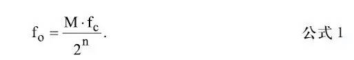
按照对应clk_12MHz的高音进行相位累加器步进的计算,切到clk_6MHz,clk_3MHz时钟频率下分别对应对应中音和低音,n位相位累加器存在2n个可能的相位点。△相位寄存器中的数字字M代表相位累加器每个时钟周期增加的数量。如果时钟频率为fc,则输出正弦波频率计算公式为:

// 高音1
reg [23:0] 	phase_acc_h1;
wire [9:0] 	dac_data_h1;
always @(posedge uclk) phase_acc_h1 <= phase_acc_h1 + 24'd1462;
lookup_tables_plus h1_lookup_tables(.phase(phase_acc_h1[23:16]), .sin_out(dac_data_h1));
// 高音2
reg [23:0] 	phase_acc_h2;
wire [9:0] 	dac_data_h2;
always @(posedge uclk) phase_acc_h2 <= phase_acc_h2 + 24'd1642;
lookup_tables_plus h2_lookup_tables(.phase(phase_acc_h2[23:16]), .sin_out(dac_data_h2));
// 高音3
reg [23:0] 	phase_acc_h3;
wire [9:0] 	dac_data_h3;
always @(posedge uclk) phase_acc_h3 <= phase_acc_h3 + 24'd1843;
lookup_tables_plus h3_lookup_tables(.phase(phase_acc_h3[23:16]), .sin_out(dac_data_h3));
// 高音4
reg [23:0] 	phase_acc_h4;
wire [9:0] 	dac_data_h4;
always @(posedge uclk) phase_acc_h4 <= phase_acc_h4 + 24'd1953;
lookup_tables_plus h4_lookup_tables(.phase(phase_acc_h4[23:16]), .sin_out(dac_data_h4));

// 高音5
reg [23:0] 	phase_acc_h5;
wire [9:0] 	dac_data_h5;
always @(posedge uclk) phase_acc_h5 <= phase_acc_h5 + 24'd2192;
lookup_tables_plus h5_lookup_tables(.phase(phase_acc_h5[23:16]), .sin_out(dac_data_h5));


// 高音6
reg [23:0] 	phase_acc_h6;
wire [9:0] 	dac_data_h6;
always @(posedge uclk) phase_acc_h6 <= phase_acc_h6 + 24'd2461;
lookup_tables_plus h6_lookup_tables(.phase(phase_acc_h6[23:16]), .sin_out(dac_data_h6));

// 高音7
reg [23:0] 	phase_acc_h7;
wire [9:0] 	dac_data_h7;
always @(posedge uclk) phase_acc_h7 <= phase_acc_h7 + 24'd2762;
lookup_tables_plus h7_lookup_tables(.phase(phase_acc_h7[23:16]), .sin_out(dac_data_h7));
5 弹奏模式逻辑
对应按键按下时触发对应的音符发生器,两个按键同时按下时进行两个音符的混音。
always @(posedge clk_in)
begin
        case (key)
        7'b1111100:PWM_DDS_accumulator1 <= PWM_DDS_accumulator1[10:0] + dac_data_h1+dac_data_h2;
        7'b1111010:PWM_DDS_accumulator1 <= PWM_DDS_accumulator1[10:0] + dac_data_h1+dac_data_h3;
        7'b1110110:PWM_DDS_accumulator1 <= PWM_DDS_accumulator1[10:0] + dac_data_h1+dac_data_h4;
        7'b1101110:PWM_DDS_accumulator1 <= PWM_DDS_accumulator1[10:0] + dac_data_h1+dac_data_h5;
        7'b1011110:PWM_DDS_accumulator1 <= PWM_DDS_accumulator1[10:0] + dac_data_h1+dac_data_h6;
        7'b0111110:PWM_DDS_accumulator1 <= PWM_DDS_accumulator1[10:0] + dac_data_h1+dac_data_h7;

        7'b1111001:PWM_DDS_accumulator1 <= PWM_DDS_accumulator1[10:0] + dac_data_h2+dac_data_h3;
        7'b1110101:PWM_DDS_accumulator1 <= PWM_DDS_accumulator1[10:0] + dac_data_h2+dac_data_h4;
        7'b1101101:PWM_DDS_accumulator1 <= PWM_DDS_accumulator1[10:0] + dac_data_h2+dac_data_h5;
        7'b1011101:PWM_DDS_accumulator1 <= PWM_DDS_accumulator1[10:0] + dac_data_h2+dac_data_h6;
        7'b0111101:PWM_DDS_accumulator1 <= PWM_DDS_accumulator1[10:0] + dac_data_h2+dac_data_h7;

        7'b1110011:PWM_DDS_accumulator1 <= PWM_DDS_accumulator1[10:0] + dac_data_h3+dac_data_h4;
        7'b1101011:PWM_DDS_accumulator1 <= PWM_DDS_accumulator1[10:0] + dac_data_h3+dac_data_h5;
        7'b1011011:PWM_DDS_accumulator1 <= PWM_DDS_accumulator1[10:0] + dac_data_h3+dac_data_h6;
        7'b0111011:PWM_DDS_accumulator1 <= PWM_DDS_accumulator1[10:0] + dac_data_h3+dac_data_h7;

        7'b1100111:PWM_DDS_accumulator1 <= PWM_DDS_accumulator1[10:0] + dac_data_h4+dac_data_h5;
        7'b1010111:PWM_DDS_accumulator1 <= PWM_DDS_accumulator1[10:0] + dac_data_h4+dac_data_h6;
        7'b0110111:PWM_DDS_accumulator1 <= PWM_DDS_accumulator1[10:0] + dac_data_h4+dac_data_h7;

        7'b1001111:PWM_DDS_accumulator1 <= PWM_DDS_accumulator1[10:0] + dac_data_h5+dac_data_h6;
        7'b0101111:PWM_DDS_accumulator1 <= PWM_DDS_accumulator1[10:0] + dac_data_h5+dac_data_h7;

        7'b0011111:PWM_DDS_accumulator1 <= PWM_DDS_accumulator1[10:0] + dac_data_h6+dac_data_h7;

        7'b0111111:PWM_DDS_accumulator1 <= PWM_DDS_accumulator1[10:0] + dac_data_h7;
        7'b1011111:PWM_DDS_accumulator1 <= PWM_DDS_accumulator1[10:0] + dac_data_h6;
        7'b1101111:PWM_DDS_accumulator1 <= PWM_DDS_accumulator1[10:0] + dac_data_h5;
        7'b1110111:PWM_DDS_accumulator1 <= PWM_DDS_accumulator1[10:0] + dac_data_h4;
        7'b1111011:PWM_DDS_accumulator1 <= PWM_DDS_accumulator1[10:0] + dac_data_h3;
        7'b1111101:PWM_DDS_accumulator1 <= PWM_DDS_accumulator1[10:0] + dac_data_h2;
        7'b1111110:PWM_DDS_accumulator1 <= PWM_DDS_accumulator1[10:0] + dac_data_h1;
        endcase
end
6 音乐播放模式逻辑
在乐曲播放模式下,会按照输入时钟节拍根据乐谱状态机去响应对应的音符。
reg [6:0] YinDiao;

always @(posedge clk_in)
begin
    if(useg_data_1[0] == 1'b1)
    begin
		   case(SongData)
			  5'b00000:begin auto_flag<=4'd1;YinDiao<=7'b1111110;PWM_DDS_accumulator2 <= PWM_DDS_accumulator2[10:0] + dac_data_h1;end
			  5'b00001:begin auto_flag<=4'd1;YinDiao<=7'b1111101;PWM_DDS_accumulator2 <= PWM_DDS_accumulator2[10:0] + dac_data_h2;end
			  5'b00010:begin auto_flag<=4'd1;YinDiao<=7'b1111011;PWM_DDS_accumulator2 <= PWM_DDS_accumulator2[10:0] + dac_data_h3;end
			  5'b00011:begin auto_flag<=4'd1;YinDiao<=7'b1110111;PWM_DDS_accumulator2 <= PWM_DDS_accumulator2[10:0] + dac_data_h4;end
			  5'b00100:begin auto_flag<=4'd1;YinDiao<=7'b1101111;PWM_DDS_accumulator2 <= PWM_DDS_accumulator2[10:0] + dac_data_h5;end
			  5'b00101:begin auto_flag<=4'd1;YinDiao<=7'b1011111;PWM_DDS_accumulator2 <= PWM_DDS_accumulator2[10:0] + dac_data_h6;end
			  5'b00110:begin auto_flag<=4'd1;YinDiao<=7'b0111111;PWM_DDS_accumulator2 <= PWM_DDS_accumulator2[10:0] + dac_data_h7;end
			  5'b00111:begin auto_flag<=4'd2;YinDiao<=7'b1111110;PWM_DDS_accumulator2 <= PWM_DDS_accumulator2[10:0] + dac_data_h1;end
			  5'b01000:begin auto_flag<=4'd2;YinDiao<=7'b1111101;PWM_DDS_accumulator2 <= PWM_DDS_accumulator2[10:0] + dac_data_h2;end
			  5'b01001:begin auto_flag<=4'd2;YinDiao<=7'b1111011;PWM_DDS_accumulator2 <= PWM_DDS_accumulator2[10:0] + dac_data_h3;end
			  5'b01010:begin auto_flag<=4'd2;YinDiao<=7'b1110111;PWM_DDS_accumulator2 <= PWM_DDS_accumulator2[10:0] + dac_data_h4;end
			  5'b01011:begin auto_flag<=4'd2;YinDiao<=7'b1101111;PWM_DDS_accumulator2 <= PWM_DDS_accumulator2[10:0] + dac_data_h5;end
			  5'b01100:begin auto_flag<=4'd2;YinDiao<=7'b1011111;PWM_DDS_accumulator2 <= PWM_DDS_accumulator2[10:0] + dac_data_h6;end
			  5'b01101:begin auto_flag<=4'd2;YinDiao<=7'b0111111;PWM_DDS_accumulator2 <= PWM_DDS_accumulator2[10:0] + dac_data_h7;end
			  5'b01110:begin auto_flag<=4'd3;YinDiao<=7'b1111110;PWM_DDS_accumulator2 <= PWM_DDS_accumulator2[10:0] + dac_data_h1;end
			  5'b01111:begin auto_flag<=4'd3;YinDiao<=7'b1111101;PWM_DDS_accumulator2 <= PWM_DDS_accumulator2[10:0] + dac_data_h2;end
			  5'b10000:begin auto_flag<=4'd3;YinDiao<=7'b1111011;PWM_DDS_accumulator2 <= PWM_DDS_accumulator2[10:0] + dac_data_h3;end
			  5'b10001:begin auto_flag<=4'd3;YinDiao<=7'b1110111;PWM_DDS_accumulator2 <= PWM_DDS_accumulator2[10:0] + dac_data_h4;end
			  5'b10010:begin auto_flag<=4'd3;YinDiao<=7'b1101111;PWM_DDS_accumulator2 <= PWM_DDS_accumulator2[10:0] + dac_data_h5;end
			  5'b10011:begin auto_flag<=4'd3;YinDiao<=7'b1011111;PWM_DDS_accumulator2 <= PWM_DDS_accumulator2[10:0] + dac_data_h6;end
			  5'b10100:begin auto_flag<=4'd3;YinDiao<=7'b0111111;PWM_DDS_accumulator2 <= PWM_DDS_accumulator2[10:0] + dac_data_h7;end
			endcase
	end
end

song1 Music1(.clk(clk_4Hz),.ifplay(useg_data_1[0]),.SongData(SongData[4:0]));
遇到的主要难题及解决方法
1 和弦失真问题,最后通过直播发现是混波的DAC寄存器位数不足的原因;
2 谐波叠加问题,主要是通过交流群里同学们的经验以及查阅相关文章最后通过波表合成的方式解决。
总结与计划
针对整个项目的完成度来说,相关的任务需求已经基本实现,由于时间关系其中的许多细节的地方都没有来得及去好好理解,包括一些直接采用的基础模块,这块后面还需要加深下理解。由于是刚入门的FPGA小白,相关的编程方式和设计思想的理解还是有很多不足的地方,包括这次的项目代码都是通过不断的下载调试,没有进行仿真相关的操作。后面活动结束后再向其他同学学习学习FPGA的编程规范和模块化编程思想等。
资源使用
Design Summary:
Number of registers: 353 out of 4635 (8%)
PFU registers: 353 out of 4320 (8%)
PIO registers: 0 out of 315 (0%)
Number of SLICEs: 793 out of 2160 (37%)
SLICEs as Logic/ROM: 793 out of 2160 (37%)
SLICEs as RAM: 0 out of 1620 (0%)
SLICEs as Carry: 266 out of 2160 (12%)
Number of LUT4s: 1586 out of 4320 (37%)
Number used as logic LUTs: 1054
Number used as distributed RAM: 0
Number used as ripple logic: 532
Number used as shift registers: 0
Number of PIO sites used: 47 + 4(JTAG) out of 105 (49%)
Number of block RAMs: 1 out of 10 (10%)
Number of GSRs: 1 out of 1 (100%)
EFB used : No
JTAG used : No
Readback used : No
Oscillator used : No
Startup used : No
POR : On
Bandgap : On
Number of Power Controller: 0 out of 1 (0%)
Number of Dynamic Bank Controller (BCINRD): 0 out of 6 (0%)
Number of Dynamic Bank Controller (BCLVDSO): 0 out of 1 (0%)
Number of DCCA: 0 out of 8 (0%)
Number of DCMA: 0 out of 2 (0%)
Number of PLLs: 0 out of 2 (0%)
Number of DQSDLLs: 0 out of 2 (0%)
Number of CLKDIVC: 0 out of 4 (0%)
Number of ECLKSYNCA: 0 out of 4 (0%)
Number of ECLKBRIDGECS: 0 out of 2 (0%)
参考链接:
- 蜂鸣器与喇叭的区别 蜂鸣器和电铃的区别-与非网 (eefocus.com)
- 无源蜂鸣器工作原理_无源蜂鸣器的优缺点_无源蜂鸣器的作用-与非网 (eefocus.com)
- 蜂鸣器和扬声器的区别是什么-电子发烧友网 (elecfans.com)
- 浅谈10种扬声器类别 (sohu.com)
- LTspice XVII超详细的官方教程汇总及解读 - 尚为网 (sunev.cn)
- 波形信号发生器设计 [电子森林] (eetree.cn)
- 简易电子琴设计 [电子森林] (eetree.cn)
- verilog_debounce [电子森林] (eetree.cn)
- dds_verilog [电子森林] (eetree.cn)
- Electric-Piano-with-FPGA
- DigitalPiano
- FPGA通过查表的方式生成正弦波
- 音频信号的基波、谐波
- 写给理工科人看的乐理