
KiCad文件
全屏
内容介绍
项目备注
视频课程
任务列表
项目报告
内容介绍
专为嵌入式系统学习而设计。
基于树莓派RP2040的嵌入式系统学习平台,可以通过C/C++以及MicroPython编程来学习嵌入式系统的工作原理和应用。
板卡适用范围:
- 适用于大一学生或嵌入式系统入门者
- 了解电子系统构成、学会一门与硬件直接相关的编程语言
- 自己动手完成有趣的项目,激发对电子的兴趣,培养自信心
- 开源资源的利用和分享意识
- 培养项目总结和展示的能力
- 搭配传感器、模拟电路外设可以完成更多创意项目,并可以做为电赛的控制、显示接口平台
提升的技能:
- MicroPython或C/C++编程、Arm Cortex M0+嵌入式系统
- 总线访问 - SPI、I2C
- 图形化信息显示 - 240 * 240 LCD
- 按键和模拟信号的输入控制
- 红外接收和控制
- 姿态传感器的使用
实物图
构成功能框图
学习平台的特点:
作为一个嵌入式系统的学习平台,首先要基于核心芯片的核心板的特点以及嵌入式系统的关键知识点来定义这款学习平台:
- 采用树莓派Pico核心芯片RP2040:
- 双核Arm Cortex M0+内核,可以运行到133MHz
- 264KB内存
- 性能强大、高度灵活的可编程IO可用于高速数字接口
- 片内温度传感器、并支持外部4路模拟信号输入,内部ADC采样率高达500Ksps、12位精度
- 支持MicroPython、C、C++编程
- 板上功能:
- 240*240分辨率的彩色IPS LCD,SPI接口,控制器为ST7789
- 四向摇杆 + 2个轻触按键 + 一个三轴姿态传感器MMA7660用做输入控制
- 板上外扩2MB Flash,预刷MicroPython的UF2固件
- 一个红外接收管 + 一个红外发射管
- 一个三轴姿态传感器MMA7660
- 一个蜂鸣器
- 双排16Pin连接器,有SPI、I2C以及2路模拟信号输入
- 可以使用MicroPython、C、C++编程
- USB Type C连接器用于供电、程序下载
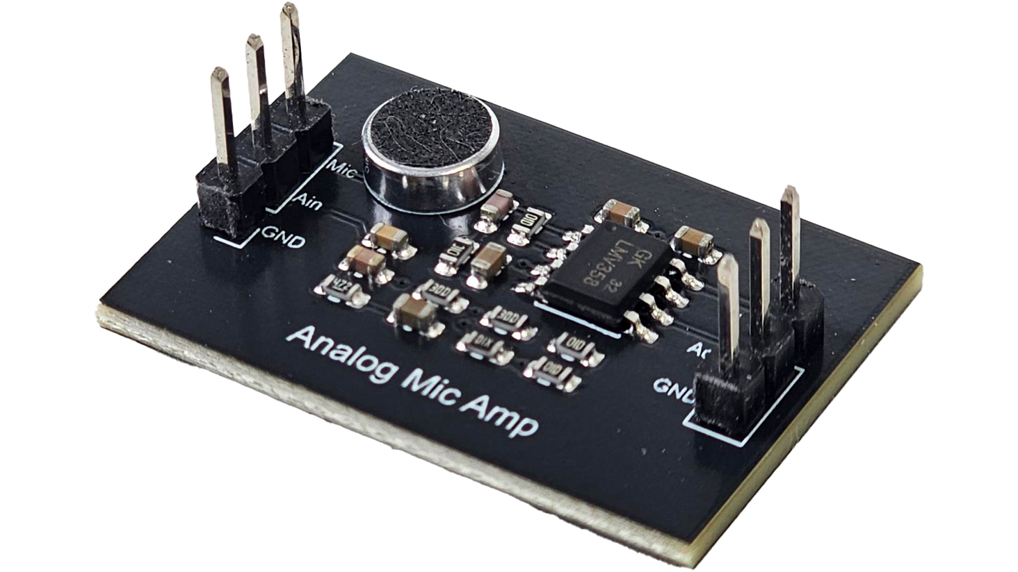
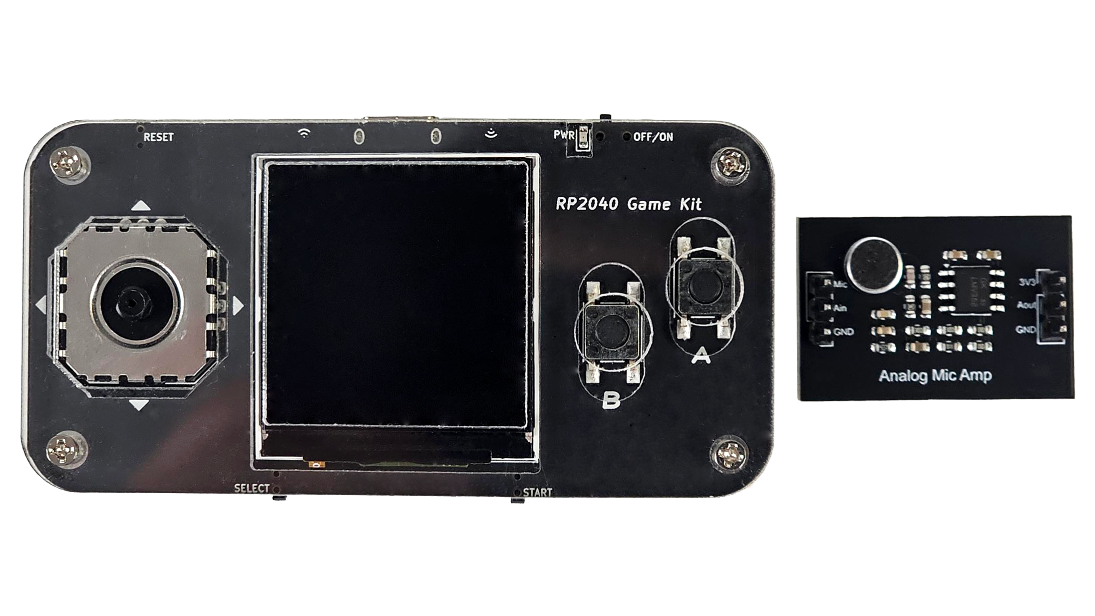
麦克风放大模块
游戏机可搭配麦克风放大电路完成一系列任务,麦克风放大模块原理图请于附件下载。
资源汇总:
- MicroPython相关资料
- MicroPython对PICO/RP2040支持的功能
- 树莓派PICO - 支持MicroPython的双核嵌入式系统模块
- 树莓派PICO做的一些项目汇总
- 基于树莓派PICO的一些项目创意
- RP2040芯片资料汇总
视频教程(含软件安装使用和亚克力的安装教程,其中涉及的代码请查阅“硬禾开源代码”链接):
硬禾开源代码:
相关课程:
注:【前三节可直接观看,无需购买,现所有课程均可观看回放,如有需要可购买课程,代码已开源在gitee库中】
点击链接 直接进入课程,在目录处点击“立即学习”,可观看课程。
注:前三节可在目录处直接点开观看,无需购买
软硬件
元器件


软件
电路图
附件下载

Gamekit_rp2040_Gerber.rar

game2040-V3-20211228.pdf
原理图,测试代码:https://gitee.com/eetree-git/RP2040_Game_Kit
mic_amp.pdf
麦克风放大模块原理图
团队介绍
苏州硬禾信息科技有限公司
评论
0 / 100
查看更多
猜你喜欢
基于树莓派RP2040的嵌入式系统学习平台制作摇杆鼠标基于树莓派RP2040的嵌入式系统学习平台制作摇杆鼠标,能够通过摇杆和按键实现鼠标的功能,包括长按、短按、拖动和滚动,并在LCD上显示鼠标图像。
3042
使用树莓派RP2040嵌入式系统学习平台设计鼠标该项目基于树莓派RP2040的嵌入式系统学习平台,使用micropython编写,最终呈现效果是模拟我们平常使用的鼠标
2663
基于树莓派RP2040的嵌入式系统学习平台设计的赛车游戏仿照经典的“公路赛车”游戏,设计的一款纵向无限挑战游戏,在有限的三条车道内利用树莓派pico板卡的加速度传感器,实现汽车的自由移动,躲避障碍车,碰撞奖励车以获得尽可能高的分数,是一款十分考验反应力的游戏。
2631
