项目要求:
1. 实现一个可定时时钟的功能,用小脚丫FPGA核心模块的4个按键设置当前的时间,OLED显示数字钟的当前时间,精确到分钟即可,到整点的时候比如8:00,蜂鸣器报警,播放音频信号,最长可持续30秒;
2. 实现温度计的功能,小脚丫通过板上的温度传感器实时测量环境温度,并同时间一起显示在OLED的屏幕上;
3. 定时时钟整点报警的同时,将温度信息通过UART传递到电脑上,电脑上能够显示当前板子上的温度信息(任何显示形式都可以),要与OLED显示的温度值一致;
4. PC收到报警的温度信号以后,将一段音频文件(自己制作,持续10秒钟左右)通过UART发送给小脚丫FPGA,蜂鸣器播放收到的这段音频文件,OLED屏幕上显示的时间信息和温度信息都停住不再更新;
5. 音频文件播放完毕,OLED开始更新时间信息和当前的温度信息
系统设计:
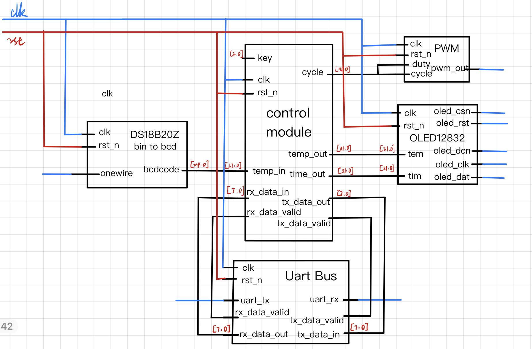
根据项目要求,完成任务需要用到OLED,测温,蜂鸣器,uart串口以及按键功能,首先完成并测试各模块代码,再通过control模块控制各个外设协同工作,实现项目要求,具体框架原理图如下:
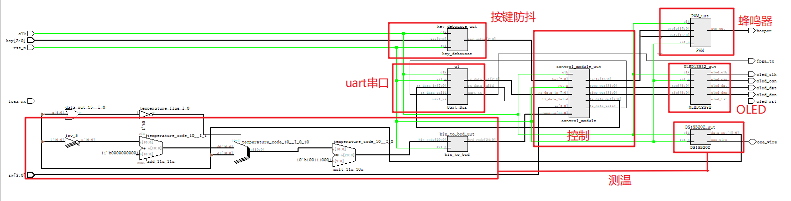
编译后生成的Netlist如图所示:
关键代码:
在做项目之前先把电子森林上的各种教程copy了一遍,大多数模块直接采用教程中的,下面主要介绍一下控制部分control_module:
首先定义模块的输入输出,设置了若干标志位,通过控制标志位来实现不同动作切换
module control_module
(
	input				clk,			// system clock
	input				rst_n,			// system reset
	input	    [3:0]	sw,
	input      	[2:0] 	key,
	input       [11:0] temp_in,

	input              	rx_data_valid,
	input       [7:0]  rx_data_in,

	output  reg 		tx_data_valid,
	output  reg [7:0]	tx_data_out,

	output  reg	[31:0]	time_out,
	output  reg	[31:0]	temp_out,

	output	reg		[15:0]	cycle
);

	reg time_buffer_flag;//开始计时
	reg time_set_flag;	//闹钟设定完毕
	reg tone_set_flag; //乐谱数据传送完毕
	reg tone_flag;    //乐谱标志位
	reg tone_finish_flag;   //乐谱结束
	reg pwm_flag;      //pwm标志位
	reg pwm_finish_flag;	   //pwm结束
	reg temp_tx_flag;  //开始传送温度数据
首先是1分钟计时,然后下面部分通过配置三个标志位来控制时间的变化。其中time_buffer为0时停止计时并检测按键变化来设置当前时间,为1时开始计时,tone_flag表示蜂鸣器开始播放,此时会停止计时
	reg [29:0] cnt_1m;
	always @(posedge clk or negedge rst_n)begin //计时一分钟
		if(!rst_n) cnt_1m <= 1'b0;
		else if(cnt_1m >= 30'd719_999_999) cnt_1m <= 1'b0;
		else cnt_1m <= cnt_1m + 1'b1;
	end


	reg time_1plus_flag;
	reg time_60plus_flag;
	reg time_plus_full;
	always@(posedge clk or negedge rst_n) begin       //*********************按键控制**************************//
		if(!rst_n)begin
			time_1plus_flag <= 1'b0;
			time_60plus_flag <= 1'b0;
			time_buffer_flag <= 1'b0;
			tone_flag <= 1'b0;
		end else begin
			if(time_buffer_flag ==1'b0)begin           //停止计时并按键设置时间
				case(key)
					3'b100:time_60plus_flag <= 1'b1;							//按键4增加时
					3'b010:time_1plus_flag <= 1'b1;								//按键3增加分
					3'b001:time_buffer_flag <= 1'b1;							//按键2开始计时
					default:begin time_1plus_flag <= 1'b0;time_60plus_flag <= 1'b0;  end
				endcase
				if(tone_finish_flag == 1'b1) begin
					tone_flag <= 1'b0;       //停止演奏
					time_buffer_flag <= 1'b1;//开始计时
				end
			end else if(tone_flag == 1'b0 )begin                              //计时
				if(cnt_1m >= 30'd719_999_999)begin
					time_1plus_flag <= 1'b1;
				end else begin
					time_1plus_flag <= 1'b0;
					time_60plus_flag <= 1'b0;
				end

				if(key == 3'b001 && tone_set_flag == 1'b1 ) begin
					tone_flag <= 1'b1;	       //开始演奏
					time_buffer_flag <= 1'b0; //停止计时
				end else begin
					tone_flag <= tone_flag ;
					time_buffer_flag <= time_buffer_flag ;
				end

			end else begin
				time_1plus_flag <= 1'b0;
				time_60plus_flag <= 1'b0;
			end

		end
	end
由于输出的时间为16进制,需要让数字按照正常时钟来变化
	reg [15:0] time_buffer;
	always@(posedge clk or negedge rst_n) begin       //**********************time+1*******************//
		if(!rst_n)begin
			time_buffer[7:0] <= 8'b0;
		end else begin
			if(time_1plus_flag)begin
				if(time_buffer[3:0] >= 4'd9 && time_buffer[7:4] < 4'd5) time_buffer[7:0] <= time_buffer[7:0] + 4'd7;
				else if(time_buffer[3:0] >= 4'd9 && time_buffer[7:4] == 4'd5) begin
					time_buffer[7:0] <= 8'b0;
					time_plus_full <= 1'b1;
				end else begin
					time_buffer[7:0] <= time_buffer[7:0] + 1'b1;
				end
			end else begin
				time_buffer[7:0] <= time_buffer[7:0];
				time_plus_full <= 1'b0;
			end
		end
	end


	always@(posedge clk or negedge rst_n) begin       //***********************time+60***************************//
		if(!rst_n)begin
			time_buffer[15:8] <= 8'b0;
		end else begin
			if(time_60plus_flag||time_plus_full)begin
				if(time_buffer[11:8] >= 4'd9 && time_buffer[15:12] < 4'd2) time_buffer[15:8] <= time_buffer[15:8] + 4'd7;
				else if(time_buffer[11:8] >= 4'd3 && time_buffer[15:12] == 4'd2) time_buffer[15:8] <= 8'b0;
				else time_buffer[15:8] <= time_buffer[15:8] + 1'b1;
			end else begin
				time_buffer[15:8] <= time_buffer[15:8];
			end
		end
	end
uart串口输入报警的时间(4位十六进制数),然后配置time_set_flag为1,表示设置完毕
	reg cnt_rx ;
	reg [15:0]time_set;
	always@(posedge clk or negedge rst_n) begin       //*****************************uart设置time_set********************//
		if(!rst_n)begin
			cnt_rx <= 1'b0;
			time_set <= 16'b0;
			time_set_flag <= 1'b0;
		end else begin
			if(rx_data_valid && time_set_flag == 0)begin
				cnt_rx <= !cnt_rx;
				if(cnt_rx == 1'b0)begin
					time_set[15:8] <= rx_data_in[7:0];
				end else begin
					time_set[7:0]  <= rx_data_in[7:0];
					time_set_flag <= 1'b1;
				end
			end else begin
				cnt_rx <= cnt_rx;
				time_set <= time_set;
			end
		end
	end
当检测到time_buffer与设定的time_set_flag相等时,报警(pwm_flag置1)并开始传送温度数据(temp_tx_flag)
	always@(posedge clk or negedge rst_n) begin       //*************************报警并uart传送温度数据***********************//
		if(!rst_n)begin
			pwm_flag <= 1'b0;
			temp_tx_flag <= 1'b0;
		end else begin
			if(tone_flag ==1'b1) begin
				temp_tx_flag <= 1'b0;
			end else if(time_buffer == time_set && time_set_flag == 1'b1)begin
				temp_tx_flag <= 1'b1;
			end else if(tone_finish_flag == 1'b1)begin
				temp_tx_flag <= 1'b1;
			end else begin
				temp_tx_flag <= temp_tx_flag;
			end

			if(pwm_finish_flag==1'b1 ) begin
				pwm_flag <= 1'b0;
			end else if(time_buffer == time_set && time_set_flag == 1'b1)begin
				pwm_flag <= 1'b1;
			end else begin
				pwm_flag <= pwm_flag ;
			end
		end
	end
temp_tx_flag置1时,开始每秒发送一次温度数据
	always @(posedge clk or negedge rst_n)begin      //*********************每秒发一个温度数据,16进制显示***********************//
		if(!rst_n) begin
			tx_data_valid <= 1'b0;
			tx_data_out <= 1'b0;
		end else begin
			if(temp_tx_flag)begin       //发送温度数据
				if(cnt_uart == 24'd11_599_999 ) begin
					tx_data_valid <= 1'b1;
					tx_data_out <= temp_in[11:4];
				end else if(cnt_uart == 24'd11_999_999 ) begin
					tx_data_valid <= 1'b1;
					tx_data_out <= {temp_in[3:0],4'b0};
				end else begin
					tx_data_valid <= 1'b0; tx_data_out <= tx_data_out;
				end
			end else begin
				tx_data_valid <= 1'b0; tx_data_out <= tx_data_out;
			end
		end
	end
制作了一个频率音符的对应表,方便串口直接输入音符A1B3C7等
always @(posedge clk or negedge rst_n)begin //***********************音符频率对应表***************************//
if(!rst_n) begin
cycle <= 8'b0;
tone_finish_flag <= 1'b0;
end else begin
case(note)
8'hA1: cycle <= 16'd45872; //L1,
8'hA2: cycle <= 16'd40858; //L2,
8'hA3: cycle <= 16'd36408; //L3,
8'hA4: cycle <= 16'd34364; //L4,
8'hA5: cycle <= 16'd30612; //L5,
8'hA6: cycle <= 16'd27273; //L6,
8'hA7: cycle <= 16'd24296; //L7,
8'hB1: cycle <= 16'd22931; //M1,
8'hB2: cycle <= 16'd20432; //M2,
8'hB3: cycle <= 16'd18201; //M3,
8'hB4: cycle <= 16'd17180; //M4,
8'hB5: cycle <= 16'd15306; //M5,
8'hB6: cycle <= 16'd13636; //M6,
8'hB7: cycle <= 16'd12148; //M7,
8'hC1: cycle <= 16'd11478; //H1,
8'hC2: cycle <= 16'd10215; //H2,
8'hC3: cycle <= 16'd9140; //H3,
8'hC4: cycle <= 16'd8598; //H4,
8'hC5: cycle <= 16'd7653; //H5,
8'hC6: cycle <= 16'd6818; //H6,
8'hC7: cycle <= 16'd6072; //H7,
8'hD1: cycle <= 16'd5730; //V1,
8'hD2: cycle <= 16'd5106; //V2,
8'hD3: cycle <= 16'd4548; //V3,
8'hD4: cycle <= 16'd4294; //V4,
8'hD5: cycle <= 16'd3826; //V5,
8'hD6: cycle <= 16'd3409; //V6,
8'hD7: cycle <= 16'd3036; //V7,
8'hFF: begin cycle <=16'd0; tone_finish_flag <= 1'b1; end
default:cycle = 16'd0;
endcase
end
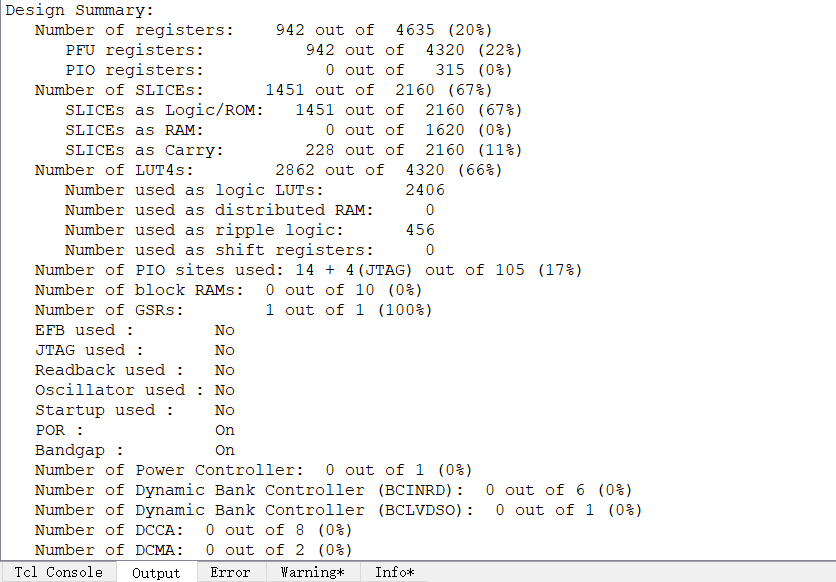
end资源占用:
项目总结:
本次实验历经两周,前一周查看各类资料,并完成各模块代码,后一周开始正式着手与项目。
在完成项目的过程中遇到的问题以及解决方法:
- 对状态机的使用不够熟练,在学校内使用VHDL做实验时更多地采用拆分各个模块来写。在写OLED时,将spi,init,writedata几个部分拆分开写不仅复杂,而且容易出错,使用状态机的方式代码简短很多,但缺点是通用性不够强
- 写OLED时将字模写到ROM中,导致资源不够用,后来直接在数组中定义了字模
- 经常出现在多个进程中需要对同一个标志位A进行置位,此时需要定义许多标志位(如finish),然后在一个单独的进程中给标志位A赋值
- 温度测量偏高,推测是温度传感器受到开发板其它元件的发热干扰
完成项目后有以下感悟:
- 必须了解FPGA的结构和性能。不同厂家,不同系列的FPGA芯片都有不同的结构和性能,但是万变不离其宗
- VHDL和verilog各有优劣,其中verilog语法与c有些许相似之处,个人使用更加方便。但是语言仅仅只是一个工具,尤其在硬件设计里,代码写得漂不漂亮,并不重要,最关键的是设计思想
- 单片机和FPGA编程完全是两种思路,既然叫做硬件描述语言,不能按照写单片机的方式,而是要“心中有电路”,各语句是并行的!
- 要充分了解各种通信协议,FPGA编写通信协议要比C语言理解更加深刻
- 相比于单片机的引脚,FPGA引脚功能更加自由,设置更加灵活