
内容介绍
内容介绍
一、项目介绍和创意介绍
1. 项目介绍
选择的是方向四:绿色能源中的自命题,双碳目标让更多的设备需要智能变频,那么如何快速地调试变频设备呢?
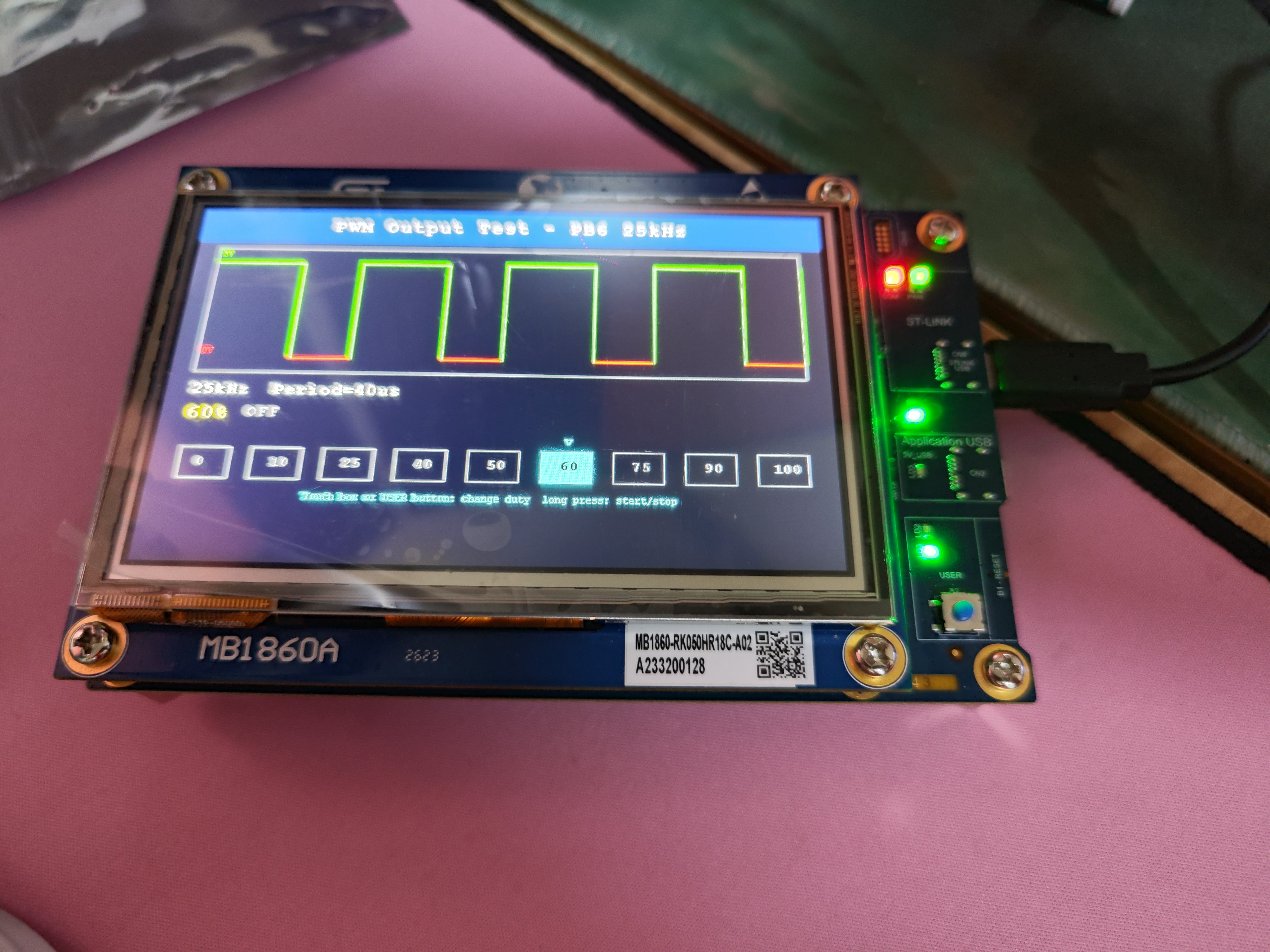
本项目基于 STM32U5G9-DK2开发板,构建了一款可视化 PWM 方波输出 GUI 终端,实现了 PWM 方波输出参数的实时调节、状态可视化及人机交互控制。
2. 创意介绍
- 可视化波形展示:将抽象的 PWM 方波以图形化方式呈现绿色为高电平,红色为低电平,直观展示占空比变化对波形的影响
- 物理按键:按键操作防止误触,适应恶劣的环境
- 预设占空比快捷调节:内置 0%、10%、25%、40%、50%、60%、75%、90%、100% 九档常用占空比,无需手动输入,提升操作效率;
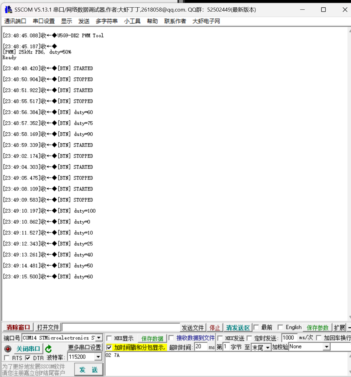
- 状态联动反馈:PWM 启停状态、占空比变化实时同步到 LCD 界面和 UART 日志,便于调试和验证。
二、使用到的硬件介绍
- 主控芯片:STM32U5G9J 微控制器,作为核心控制单元,负责 PWM 生成、触摸屏 / LCD 驱动、按键交互逻辑处理;
- 显示模块:STM32U5G9J Discovery 开发板自带 LCD 屏(分辨率 800×480),用于 GUI 界面和 PWM 波形绘制;
- 触摸模块:GT911 电容触摸屏(通过 I2C2 通信),实现触控选占空比功能;
- PWM 输出模块:TIM4_CH1(PB6 引脚),配置为 25kHz 固定频率 PWM 输出通道;
- 输入模块:USER 物理按键(PC13 引脚),支持短按切换占空比、长按启停 PWM;
- 调试模块:UART1 串口,输出操作日志和触摸屏诊断信息,便于开发调试。
三、方案框图和项目设计思路介绍
1. 方案框图
┌───────────────┐     ┌───────────────┐     ┌───────────────┐
│ 输入模块      │     │ 主控模块      │     │ 输出模块      │
│ ┌───────────┐ │     │ ┌───────────┐ │     │ ┌───────────┐ │
│ │ 触摸屏(GT911)│─────┼─┤ STM32U5G9J │─────┼─┤ LCD显示屏  │ │
│ └───────────┘ │     │ └───────────┘ │     │ └───────────┘ │
│ ┌───────────┐ │     │        │       │     │ ┌───────────┐ │
│ │ USER按键  │ │     │        │       │     │ │ PWM输出(PB6)│ │
│ └───────────┘ │     │        │       │     │ └───────────┘ │
└───────────────┘     │        │       │     └───────────────┘
                      │        ▼       │
                      │ ┌───────────┐ │     ┌───────────────┐
                      │ │ UART1调试 │ ├─────┤ 日志输出      │
                      │ └───────────┘ │     └───────────────┘
                      └───────────────┘
2. 项目设计思路
实现 GUI 交互逻辑(pwm_gui.c/h),包括波形绘制、界面刷新、触控 / 按键事件处理。PC13 引脚配置为输入模式,检测电平变化识别按键操作。通过 UART1 输出操作日志。
四、软件流程图和关键代码介绍
1. 软件流程图
┌─────────────────────────┐
│ 系统初始化(HAL/时钟)  │
└───────────┬─────────────┘
            ▼
┌─────────────────────────┐
│ 外设初始化              │
│ (PWM/LCD/触摸屏/UART/按键)│
└───────────┬─────────────┘
            ▼
┌─────────────────────────┐
│ GUI初始化(DrawAll)    │
│ - 设置初始占空比(50%)    │
│ - 绘制初始界面/波形      │
└───────────┬─────────────┘
            ▼
┌─────────────────────────┐
│ 主循环:PWM_GUI_Process │
├───────────┬─────────────┤
│ 				按键检测
├───────────┼─────────────┤
│ 短按:切换占空比         │
│ 长按:启停PWM           │
├───────────┼─────────────┤
│ 触控:匹配占空比预设框   │
├───────────┼─────────────┤
│ 参数变化?→ 是:更新PWM  │
│            → 否:继续循环│
├───────────┼─────────────┤
│ 重绘波形/信息栏          │
│ UART输出日志             │
└───────────┬─────────────┘
            ▼
└─────────────────────────┘
2. 关键代码介绍
pwm_out.c代码,负责定时器4的初始化和输出配置
#include "pwm_out.h"

/* PB6 = TIM4_CH1, AF2 */
static TIM_HandleTypeDef htim4;
static uint8_t current_duty;

void PWM_Out_Init(void)
{
  GPIO_InitTypeDef GPIO_InitStruct = {0};

  __HAL_RCC_TIM4_CLK_ENABLE();
  __HAL_RCC_GPIOB_CLK_ENABLE();

  GPIO_InitStruct.Pin       = GPIO_PIN_6;
  GPIO_InitStruct.Mode      = GPIO_MODE_AF_PP;
  GPIO_InitStruct.Pull      = GPIO_NOPULL;
  GPIO_InitStruct.Speed     = GPIO_SPEED_FREQ_HIGH;
  GPIO_InitStruct.Alternate = GPIO_AF2_TIM4;
  HAL_GPIO_Init(GPIOB, &GPIO_InitStruct);

  htim4.Instance           = TIM4;
  htim4.Init.Prescaler     = PWM_TIM_PSC;
  htim4.Init.CounterMode   = TIM_COUNTERMODE_UP;
  htim4.Init.Period        = PWM_TIM_ARR;
  htim4.Init.ClockDivision = TIM_CLOCKDIVISION_DIV1;
  htim4.Init.AutoReloadPreload = TIM_AUTORELOAD_PRELOAD_ENABLE;
  HAL_TIM_PWM_Init(&htim4);

  TIM_OC_InitTypeDef sConfigOC = {0};
  sConfigOC.OCMode     = TIM_OCMODE_PWM1;
  sConfigOC.Pulse      = 0;
  sConfigOC.OCPolarity = TIM_OCPOLARITY_HIGH;
  sConfigOC.OCFastMode = TIM_OCFAST_DISABLE;
  HAL_TIM_PWM_ConfigChannel(&htim4, &sConfigOC, TIM_CHANNEL_1);

  current_duty = 0;
}

void PWM_Out_SetDuty(uint8_t duty_percent)
{
  if (duty_percent > 100) duty_percent = 100;
  __HAL_TIM_SET_COMPARE(&htim4, TIM_CHANNEL_1, (uint32_t)duty_percent);
  current_duty = duty_percent;
}

uint8_t PWM_Out_GetDuty(void)
{
  return current_duty;
}

void PWM_Out_Start(void)
{
  HAL_TIM_PWM_Start(&htim4, TIM_CHANNEL_1);
}

void PWM_Out_Stop(void)
{
  HAL_TIM_PWM_Stop(&htim4, TIM_CHANNEL_1);
}
pwm_gui.c代码,负责联动PWM信号和GUI显示部分
#include "pwm_gui.h"
#include "pwm_out.h"
#include "stm32u5g9j_discovery_lcd.h"
#include "stm32u5g9j_discovery_ts.h"
#include "stm32_lcd.h"
#include <string.h>

extern UART_HandleTypeDef huart1;
extern __IO uint16_t x;
extern __IO uint16_t y;
extern TS_State_t TS_State;

static void PG_Send(const char *str)
{
  HAL_UART_Transmit(&huart1, (uint8_t *)str, strlen(str), HAL_MAX_DELAY);
}

static void PG_SendU32(uint32_t val)
{
  char buf[12];
  int i = 0;
  if (val == 0) { buf[0] = '0'; i = 1; }
  else { while (val) { buf[i++] = '0' + (val % 10); val /= 10; } }
  for (int j = 0; j < i / 2; j++)
  { char t = buf[j]; buf[j] = buf[i-1-j]; buf[i-1-j] = t; }
  buf[i] = '\0';
  PG_Send(buf);
}

/* Duty cycle presets */
static const uint8_t duty_tab[] = { 0, 10, 25, 40, 50, 60, 75, 90, 100 };
#define DUTY_N  (sizeof(duty_tab)/sizeof(duty_tab[0]))

static uint8_t step;
static uint8_t duty;
static uint8_t run;
static uint8_t btn_prev;

/* ---- Draw waveform: 4 cycles, green=HIGH 5V, red=LOW 0V ---- */
static void DrawWave(void)
{
  uint32_t cyc = 740 / 4;
  uint32_t hi = (cyc * duty) / 100;
  uint32_t lo = cyc - hi;
  uint32_t base = 220, top = 80;

  UTIL_LCD_FillRect(30, 60, 740, 180, UTIL_LCD_COLOR_BLACK);
  UTIL_LCD_DrawRect(29, 59, 742, 182, UTIL_LCD_COLOR_GRAY);

  for (int c = 0; c < 4; c++)
  {
    uint32_t xp = 30 + c * cyc;
    if (hi > 0)
    {
      UTIL_LCD_DrawHLine(xp, top, hi, UTIL_LCD_COLOR_GREEN);
      UTIL_LCD_DrawHLine(xp, top + 1, hi, UTIL_LCD_COLOR_GREEN);
      UTIL_LCD_DrawVLine(xp + hi, top, base - top, UTIL_LCD_COLOR_GREEN);
      UTIL_LCD_DrawVLine(xp + hi + 1, top, base - top, UTIL_LCD_COLOR_GREEN);
    }
    if (lo > 0)
    {
      UTIL_LCD_DrawHLine(xp + hi, base, lo, UTIL_LCD_COLOR_RED);
      UTIL_LCD_DrawHLine(xp + hi, base - 1, lo, UTIL_LCD_COLOR_RED);
    }
    if (c < 3)
    {
      UTIL_LCD_DrawVLine(xp + cyc, top, base - top, UTIL_LCD_COLOR_GREEN);
      UTIL_LCD_DrawVLine(xp + cyc + 1, top, base - top, UTIL_LCD_COLOR_GREEN);
    }
  }

  UTIL_LCD_SetFont(&Font12);
  UTIL_LCD_SetTextColor(UTIL_LCD_COLOR_GREEN);
  UTIL_LCD_DisplayStringAt(32, 62, (uint8_t *)"5V", LEFT_MODE);
  UTIL_LCD_SetTextColor(UTIL_LCD_COLOR_RED);
  UTIL_LCD_DisplayStringAt(32, base - 15, (uint8_t *)"0V", LEFT_MODE);
}

/* ---- Draw info + step boxes ---- */
static void DrawInfo(void)
{
  /* Clear area */
  UTIL_LCD_FillRect(0, 250, 800, 230, UTIL_LCD_COLOR_BLACK);

  /* Line 1: freq */
  UTIL_LCD_SetFont(&Font20);
  UTIL_LCD_SetBackColor(UTIL_LCD_COLOR_BLACK);
  UTIL_LCD_SetTextColor(UTIL_LCD_COLOR_WHITE);
  UTIL_LCD_DisplayStringAt(30, 255, (uint8_t *)"25kHz  Period=40us", LEFT_MODE);

  /* Line 2: big duty number */
  UTIL_LCD_SetFont(&Font24);
  UTIL_LCD_SetTextColor(UTIL_LCD_COLOR_YELLOW);
  char buf[20];
  int idx = 0;
  if (duty >= 100) buf[idx++] = '1';
  if (duty >= 10)  buf[idx++] = '0' + (duty / 10) % 10;
  buf[idx++] = '0' + duty % 10;
  buf[idx++] = '%';
  buf[idx] = '\0';
  UTIL_LCD_DisplayStringAt(30, 285, (uint8_t *)buf, LEFT_MODE);

  UTIL_LCD_SetFont(&Font20);
  UTIL_LCD_SetTextColor(run ? UTIL_LCD_COLOR_GREEN : UTIL_LCD_COLOR_GRAY);
  UTIL_LCD_DisplayStringAt(100, 285,
    run ? (uint8_t *)"ON  PB6 active" : (uint8_t *)"OFF", LEFT_MODE);

  /* ---- Step bar: 9 boxes ---- */
  int32_t box_y = 340;
  int32_t box_w = 60;
  int32_t box_h = 40;
  int32_t box_gap = 24;
  int32_t bar_w = DUTY_N * box_w + (DUTY_N - 1) * box_gap;
  int32_t bar_x = (800 - bar_w) / 2;

  const char *labels[] = {"0", "10", "25", "40", "50", "60", "75", "90", "100"};

  for (uint32_t i = 0; i < DUTY_N; i++)
  {
    int32_t bx = bar_x + i * (box_w + box_gap);

    if (i == step)
    {
      /* Selected: filled cyan box, black text */
      UTIL_LCD_FillRect(bx, box_y, box_w, box_h, UTIL_LCD_COLOR_CYAN);
      UTIL_LCD_SetBackColor(UTIL_LCD_COLOR_CYAN);
      UTIL_LCD_SetTextColor(UTIL_LCD_COLOR_BLACK);
    }
    else
    {
      /* Unselected: gray outline, gray text */
      UTIL_LCD_FillRect(bx, box_y, box_w, box_h, UTIL_LCD_COLOR_BLACK);
      UTIL_LCD_DrawRect(bx, box_y, box_w, box_h, UTIL_LCD_COLOR_GRAY);
      UTIL_LCD_SetBackColor(UTIL_LCD_COLOR_BLACK);
      UTIL_LCD_SetTextColor(UTIL_LCD_COLOR_GRAY);
    }

    UTIL_LCD_SetFont(&Font16);
    /* center label */
    int32_t len = (labels[i][2] != '\0') ? 3 : (labels[i][1] != '\0') ? 2 : 1;
    int32_t tw = len * 8;
    UTIL_LCD_DisplayStringAt(bx + (box_w - tw) / 2, box_y + 12, (uint8_t *)labels[i], LEFT_MODE);
  }

  /* Down arrow above selected box */
  UTIL_LCD_SetBackColor(UTIL_LCD_COLOR_BLACK);
  UTIL_LCD_SetFont(&Font16);
  UTIL_LCD_SetTextColor(UTIL_LCD_COLOR_CYAN);
  int32_t arrow_x = bar_x + step * (box_w + box_gap) + box_w / 2 - 4;
  UTIL_LCD_DisplayStringAt(arrow_x, box_y - 20, (uint8_t *)"v", LEFT_MODE);

  /* Hint */
  UTIL_LCD_SetFont(&Font12);
  UTIL_LCD_SetTextColor(UTIL_LCD_COLOR_CYAN);
  UTIL_LCD_DisplayStringAt(0, box_y + box_h + 15,
    (uint8_t *)"Touch box or USER button: change duty  long press: start/stop", CENTER_MODE);
}

static void DrawAll(void)
{
  UTIL_LCD_Clear(LCD_COLOR_BLACK);

  UTIL_LCD_SetFont(&Font24);
  UTIL_LCD_SetBackColor(LCD_COLOR_ARGB8888_ST_BLUE_DARK);
  UTIL_LCD_SetTextColor(UTIL_LCD_COLOR_WHITE);
  UTIL_LCD_FillRect(0, 0, 800, 50, LCD_COLOR_ARGB8888_ST_BLUE_DARK);
  UTIL_LCD_DisplayStringAt(0, 12, (uint8_t *)"PWM Output Test - PB6 25kHz", CENTER_MODE);

  UTIL_LCD_SetBackColor(UTIL_LCD_COLOR_BLACK);
  DrawWave();
  DrawInfo();
}

/* ---- Public ---- */

void PWM_GUI_Init(void)
{
  step = 4;
  duty = duty_tab[step];
  run = 0;
  btn_prev = 0;

  PWM_Out_Init();
  PWM_Out_SetDuty(duty);

  DrawAll();

  PG_Send("\r\n[PWM] 25kHz PB6, duty=");
  PG_SendU32(duty);
  PG_Send("%\r\n");
}

/* Step box layout (must match DrawInfo) */
#define BOX_Y   340
#define BOX_W   60
#define BOX_H   40
#define BOX_GAP 24
#define BAR_W   (DUTY_N * BOX_W + (DUTY_N - 1) * BOX_GAP)
#define BAR_X   ((800 - BAR_W) / 2)

void PWM_GUI_Process(void)
{
  static uint32_t t0 = 0;
  static uint8_t down = 0;
  uint8_t btn;
  int need_redraw = 0;

  /* ---- USER button (PC13) ---- */
  btn = (HAL_GPIO_ReadPin(GPIOC, GPIO_PIN_13) == GPIO_PIN_RESET) ? 1 : 0;

  if (btn && !down) { t0 = HAL_GetTick(); down = 1; }

  if (!btn && down)
  {
    uint32_t ms = HAL_GetTick() - t0;
    down = 0;

    if (ms > 600)
    {
      run = !run;
      if (run) { PWM_Out_SetDuty(duty); PWM_Out_Start(); }
      else     { PWM_Out_Stop(); }
      PG_Send(run ? "[BTN] STARTED\r\n" : "[BTN] STOPPED\r\n");
      need_redraw = 1;
    }
    else
    {
      step++;
      if (step >= DUTY_N) step = 0;
      duty = duty_tab[step];
      if (run) PWM_Out_SetDuty(duty);
      PG_Send("[BTN] duty=");
      PG_SendU32(duty);
      PG_Send("\r\n");
      need_redraw = 1;
    }
  }

  /* ---- Touch: click step box directly ---- */
  if (TS_State.TouchDetected)
  {
    uint32_t tx = x;
    uint32_t ty = y;
    TS_State.TouchDetected = 0;

    PG_Send("[TS] X=");
    PG_SendU32(tx);
    PG_Send(" Y=");
    PG_SendU32(ty);
    PG_Send("\r\n");

    /* Check if touch is in step bar area */
    if (ty >= BOX_Y && ty <= BOX_Y + BOX_H)
    {
      if (tx >= BAR_X && tx <= BAR_X + BAR_W)
      {
        int32_t pos = tx - BAR_X;
        int32_t slot_w = BOX_W + BOX_GAP;
        uint8_t hit = pos / slot_w;
        if (hit >= DUTY_N) hit = DUTY_N - 1;

        if (hit != step)
        {
          step = hit;
          duty = duty_tab[step];
          if (run) PWM_Out_SetDuty(duty);
          PG_Send("[TS] touch step=");
          PG_SendU32(duty);
          PG_Send("%\r\n");
          need_redraw = 1;
        }
      }
    }
  }

  /* ---- Redraw if needed ---- */
  if (need_redraw)
  {
    DrawWave();
    DrawInfo();
  }
}
五、功能展示图及说明(文字描述)
工程截图
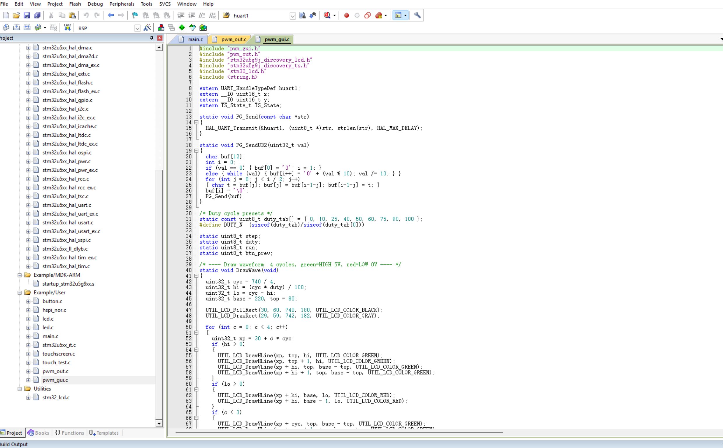
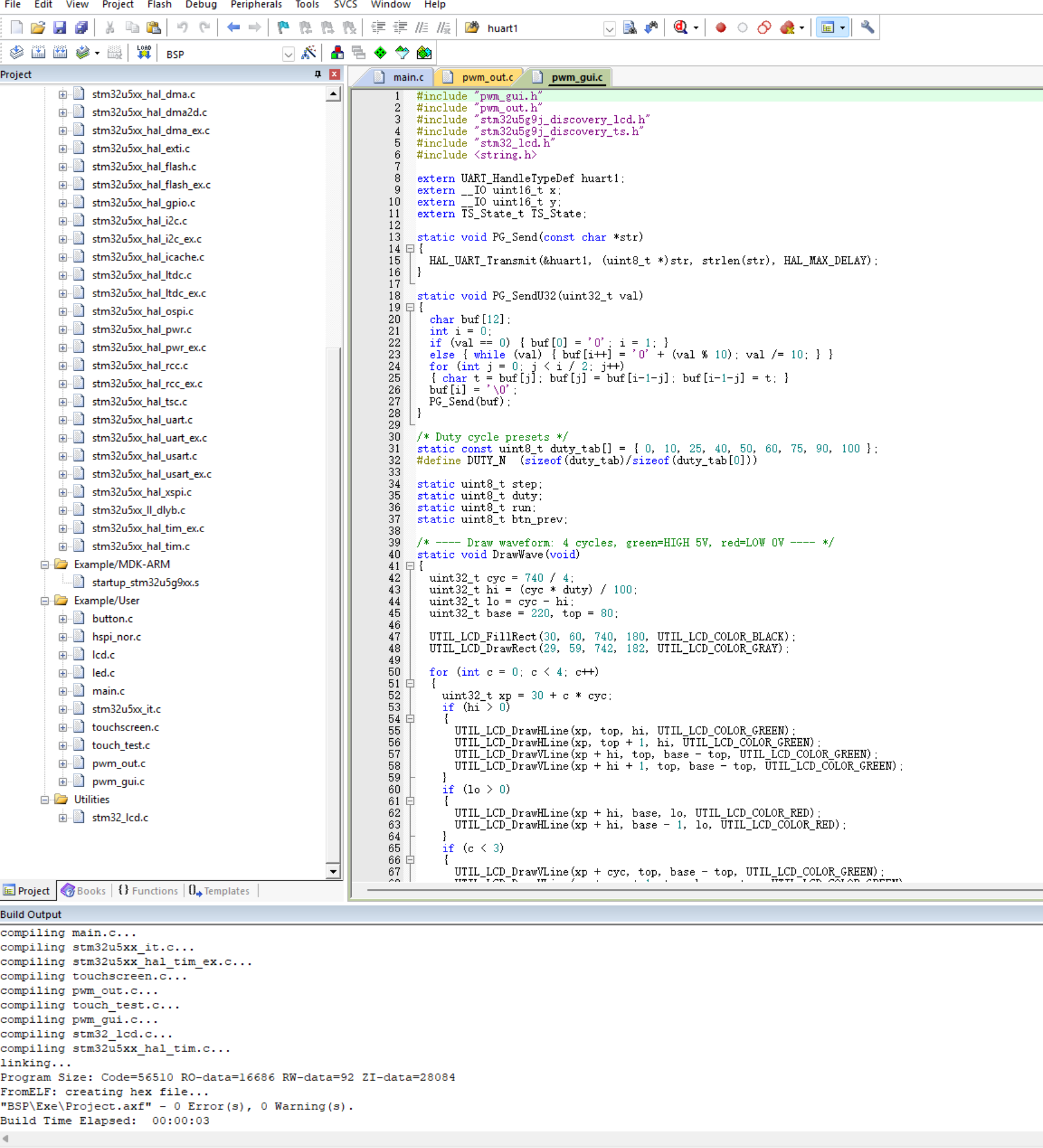
编译没问题
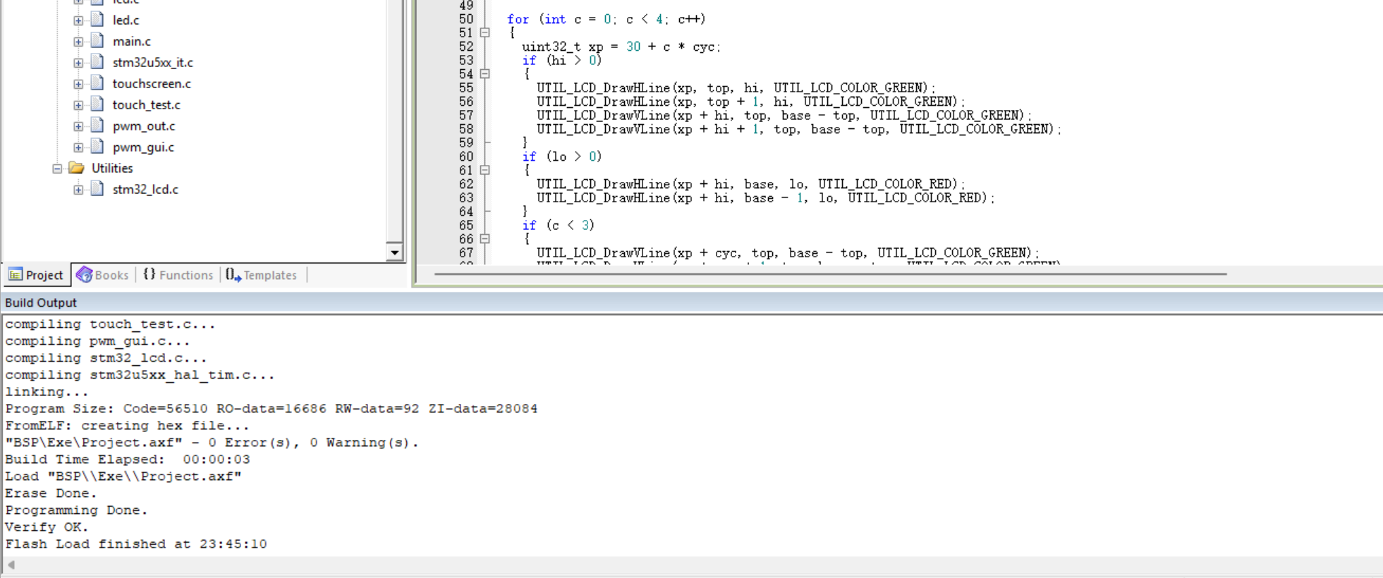
使用板载的STLINK,快速完成烧录
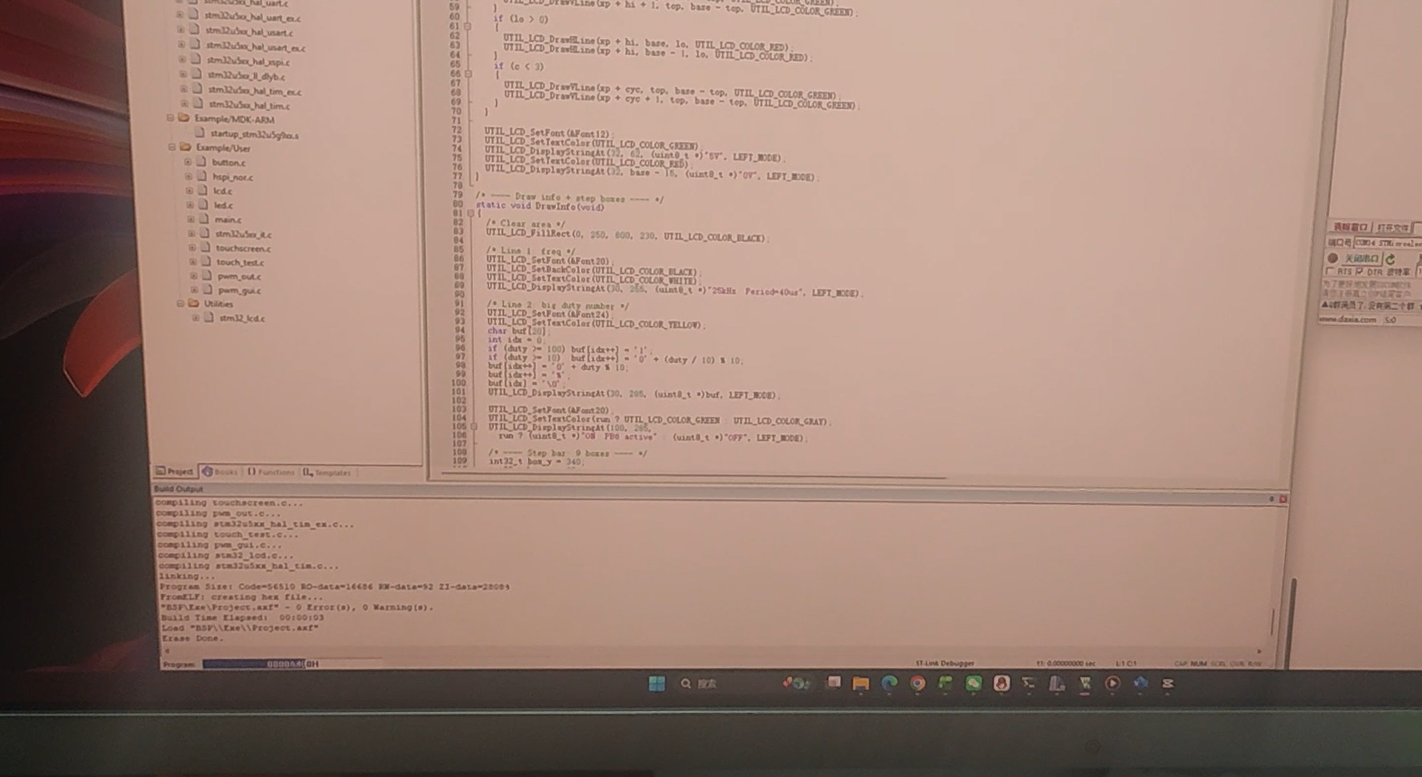
正在烧录
程序运行
串口助手打印的日志,每次按钮按下,PWM发出的波形有变化,都会有串口打印
六、难点和体会
难点:PWM 波形绘制与实际占空比不一致
LCD 绘制的波形占空比与实际 PWM 输出比例不符,通过将波形周期的像素宽度(740px)平均分为 4 个周期,每个周期的像素宽度固定为740/4。占空比到像素的转换采用整数运算:hi = (cyc * duty) / 100,保证比例精准。绘制前清空波形区,避免残留像素干扰视觉效果。
体会:
DK开发板作为ST最丰富外设的开发板,到手即用的屏幕和丰富的BSP包,十分方便开发。不管是丰富外设的DK板子和普通的Nucleo开发板都有STLINKV3,一根线就可以完成SWD下载和调试,十分方便!
附件下载

按钮控制PWM方波波形 .hex

U5G9DK2-PWM.zip
团队介绍
独立完成
评论
0 / 100
查看更多
猜你喜欢
制作FPGA电子琴1. 存储一段音乐,并可以进行音乐播放,
2. 可以自己通过板上的按键进行弹奏,支持两个按键同时按下(和弦)并且声音不能失真,板上的按键只有13个,可以通过有上方的“上“、”下”两个按键对音程进行扩展
 john
john2936
M-Design设计竞赛 - zigbee调试器该项目使用了ESP32-C6,实现了zigbee调试器的设计,它的主要功能为:在esp32-c6实现了一个串口REPL的功能,根据串口输入指令,可以作为zigbee调试器来调试zigbee设备。
_剑山1451
2026 M-Design设计竞赛 - 基于U5G9DK2的智能家居大屏音响姿态感知该项目使用了U5G9DK2和LSM6DSO,实现了智能家居大屏音响姿态感知的设计,它的主要功能为:读取陀螺仪的姿态,可显示在LCD屏幕上。
 zhjlmt
158