一、项目介绍
使用硬禾RP2350核心板以及综合扩展训练板,实现一个简易的PWM蜂鸣器音乐播放器,并由按键控制切换音乐。同时,在OLED屏幕上显示汉字音频名称。
二、硬件介绍
RP2350微处理器是树莓派基金会推出的一款双核微处理器。树莓派基金会(Raspberry Pi Foundation)于2009年在英国成立,最初是一个以教育为核心的非营利组织,旨在通过低成本硬件设备降低计算机科学教育的门槛。其首款产品Raspberry Pi 1于2012年发布后,迅速从教育工具扩展到创客、工业控制及边缘计算领域,成为全球单板计算机的标杆。随着硬件需求的多样化,基金会于2021年推出了首款自研微控制器芯片RP2040,标志着其从“提供成品开发板”向“设计底层芯片”的战略转型。这一转变不仅巩固了其在嵌入式领域的影响力,也为后续技术迭代(如RP2350)奠定了基础。基金会的核心愿景始终围绕教育普惠、开源生态构建以及推动低成本硬件在工业和消费领域的普及,其产品设计始终以“高性价比”和“易用性”为核心理念。
2021年,树莓派基金会推出了一款32位微控制器芯片,其设计目标是为教育、创客及低成本控制场景提供灵活且易于上手的解决方案。该芯片采用双核ARM Cortex-M0+架构,主频133MHz,配备264KB片上SRAM,并通过外部QSPI闪存扩展存储。其一大特色是集成可编程I/O(PIO)模块,允许开发者通过软件定义硬件协议(如控制WS2812 LED灯带或自定义传感器通信),显著降低了复杂外设的开发难度。RP2040的硬件设计兼顾成本与性能,基于其打造的Pico开发板售价仅4美元,迅速成为入门级嵌入式开发的热门选择。尽管其算力和存储有限,但其开源生态(支持MicroPython和C/C++)以及丰富的引脚配置,使其在教学实验、简单机器人控制、物联网节点等领域得到了广泛应用。
RP2350作为RP2040的升级版,于2024年发布,针对性能、安全性和扩展性进行了全面优化,以满足更复杂的应用需求。其核心架构提供两种选择:双核ARM Cortex-M33或双核RISC-V(Hazard3 32IMAC),主频提升至150MHz,并配备520KB片上SRAM,显著提升了数据处理能力和存储效率。RP2350与上代相同,基于QSPI外置Flash扩展存储,另有型号集成2MB的片内堆叠闪存。Cortex-M33内核支持浮点运算与ARM TrustZone安全扩展,适用于需要加密通信或安全启动的工业场景;RISC-V版本则强化了开源生态兼容性,为开发者提供更高的定制自由度。此外,RP2350的外设能力全面升级,GPIO数量分版本增至30或48路,PWM通道扩展至24路,PIO状态机从8个增至12个,能够并行处理更多高速外设协议。这些改进使其不仅适用于RP2040的经典场景(如教育实验和简单控制),还能胜任边缘AI推理(如语音关键词识别)、复杂机器人系统(多轴电机控制)以及工业物联网(安全数据采集)等高要求任务。通过保持与RP2040的引脚兼容性,RP2350进一步降低了升级成本,巩固了树莓派在嵌入式领域的全栈生态布局。
硬禾RP2350核心板板载了8颗矩阵单色LED、2颗WS2812 RGB LED、1颗独立单色LED、2个7段数码管、4个拨码开关、4个轻触按键和一片KXTJ3-1057三轴加速度传感器,并引出了剩余GPIO引脚,充分利用RP2350B芯片GPIO数量的优势,实现了丰富的板载资源与优秀拓展性共存。
配套的综合扩展训练板是原StepFPGA核心板系列的配套拓展板,由于硬禾RP2350核心板兼容StepFPGA核心板系列的引脚排布,因此可以直接使用。其包含一块OLED、一个蜂鸣器、一个温度传感器、一个ADC和一个DAC网络,并板载了USB-TTL转换以方便进行串口下载调试。
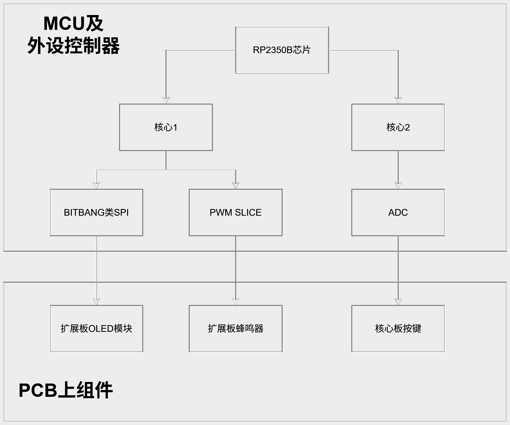
三、系统架构
在Pico SDK平台上使用C++语言编程,在RP2350B的第一个核心上通过PWM产生不同的音调,并驱动板上蜂鸣器将音调输出,同时在OLED屏幕上显示汉字信息。另外,还需支持板上按键切换几首不同的音乐,并进行按键消抖处理,这部分逻辑在第二个核心上运行。
四、软件架构
在核心1上运行初始化代码、PWM控制代码以及OLED控制代码,而核心2负责持续进行ADC转换、按键消抖算法并将结果通过跨核IPC通知核心1。核心1接到IPC消息后切换音乐,并更新对应的OLED屏幕显示信息。
五、硬件连接
由于核心板与扩展板配套,仅需连接二者,再使用Type-C数据线将核心板与PC连接即可。
六、软件代码和结构
软件部分分为几个文件,其中main.cpp为入口文件,负责初始化和拉起第二核心,以及主循环中的oled上层逻辑控制。oled.cpp中包含了OLED初始化和通信的一些底层代码。key.cpp中包含了在核心2上运行的ADC按键及其消抖逻辑。其余文件包括了一些辅助函数和数据数组。主要代码如下:
// main.cpp:
#include "common.h"

#include "hardware/clocks.h"
#include "hardware/pwm.h"
#include "hardware/uart.h"
#include "pico/multicore.h"
#include <stdio.h>

const uint _PWM_GPIO_SLICE_NUM(uint pin) { return PWM_GPIO_SLICE_NUM(pin); }

extern void gpio_init_out(uint pin, bool initial);
extern void oled_init();
extern void oled_disp();
extern void oled_show_num(uint8_t i);
extern void thread1();
extern const int8_t *SONG_DATA[];
extern const int8_t SONG_BASE[];
extern const int8_t SONG_COUNT;
extern const uint16_t note_table[];

#define dbg(x)                                                                 \
  if (logo_cnt == 0)                                                           \
  printf("%s\n", x)

// PWM slice:  GPIO0,1,16,17->SLICE0  GPIO2,3,18,19->SLICE1  GPIO32,33->SLICE8
#define BUZZER_PIN 20 // 20
#define LED_PIN 3
#define LED_IO1_PIN 27
#define LED_IO2_PIN 26
#define LED_IO3_PIN 25
#define LED_IO4_PIN 24
const uint BUZZER_PWM_SLICE = _PWM_GPIO_SLICE_NUM(BUZZER_PIN);
const uint LED_IO1_PWM_SLICE = _PWM_GPIO_SLICE_NUM(LED_IO1_PIN);
const uint LED_IO2_PWM_SLICE = _PWM_GPIO_SLICE_NUM(LED_IO2_PIN);
const uint LED_IO3_PWM_SLICE = _PWM_GPIO_SLICE_NUM(LED_IO3_PIN);
const uint LED_IO4_PWM_SLICE = _PWM_GPIO_SLICE_NUM(LED_IO4_PIN);

#define IO4_PWM_TEST 0

int main() {

  stdio_init_all();

  {
    volatile int dummy;
    const int max_wait_sec = 5;
    // timeout after XXXs if no usb-uart connected
    for (int i = 0; i < max_wait_sec; i++) {
      printf("Waiting for keypress %d/%d ...\n", i, max_wait_sec);
      dummy = getchar_timeout_us(1000000);
      if (dummy >= 0)
        break;
    }
  }
  printf("System Clock Frequency is %d Hz\n", clock_get_hz(clk_sys));
  printf("USB Clock Frequency is %d Hz\n", clock_get_hz(clk_usb));

  oled_init();

  multicore_launch_core1(thread1);

  sleep_ms(10);

  gpio_init_out(BUZZER_PIN, 0);
  gpio_init_out(LED_PIN, 0);
  gpio_init_out(LED_IO1_PIN, 1);
  gpio_init_out(LED_IO2_PIN, 1);
  gpio_init_out(LED_IO3_PIN, 1);
  gpio_init_out(LED_IO4_PIN, 1);

  // PWM
  gpio_set_function(LED_IO1_PIN, GPIO_FUNC_PWM);
  pwm_set_output_polarity(LED_IO1_PWM_SLICE, true, true);
  pwm_set_wrap(LED_IO1_PWM_SLICE, 60000);
  pwm_set_clkdiv(LED_IO1_PWM_SLICE, 200.0);
  pwm_set_chan_level(LED_IO1_PWM_SLICE,
                     LED_IO1_PIN & 1 ? PWM_CHAN_B : PWM_CHAN_A, 30000);
  // pwm_set_enabled(LED_IO1_PWM_SLICE, true);

  gpio_set_function(BUZZER_PIN, GPIO_FUNC_PWM);
  pwm_set_output_polarity(LED_IO1_PWM_SLICE, true, true);
  pwm_set_wrap(BUZZER_PWM_SLICE, 60000);
  pwm_set_clkdiv(BUZZER_PWM_SLICE, 252.0); // 595238Hz
  pwm_set_chan_level(BUZZER_PWM_SLICE, BUZZER_PIN & 1 ? PWM_CHAN_B : PWM_CHAN_A,
                     150);
  pwm_set_enabled(BUZZER_PWM_SLICE, false);

  oled_disp();
  sleep_ms(500);

  multicore_fifo_drain();

  int cur_song = 0;
  while (true) {
    oled_show_num(cur_song);
    const int8_t *song = SONG_DATA[cur_song];
    const int8_t base = SONG_BASE[cur_song];

    bool song_switch = false;
    while (!song_switch) {
      absolute_time_t note_start = get_absolute_time();

      if (*song == 127) {
        pwm_set_enabled(BUZZER_PWM_SLICE, false);
      } else {
        if (*song == 126) {
          pwm_set_enabled(BUZZER_PWM_SLICE, false);

        } else {
          int note = *song + base;
          pwm_set_wrap(BUZZER_PWM_SLICE, note_table[note]);
          pwm_set_enabled(BUZZER_PWM_SLICE, true);
        }
        song++;
      }

      while (get_absolute_time() - note_start < 270000) {
        uint32_t d;
        if (multicore_fifo_pop_timeout_us(1000, &d)) {
          printf("Got key %d\n", d);
          if (d < 120) {
            song_switch = true;
            if (++cur_song >= SONG_COUNT) {
              cur_song = 0;
            }
            break;
          }
        }
      }
    }
  }

  while (true)
    ;
}

// oled.cpp:
#include "common.h"

// OLED: CLK=45 DIN=44 RES=43 D/C=42 CS=41  D/C low=command,high=data
#define OLED_CS_PIN 41
#define OLED_DC_PIN 42
#define OLED_RST_PIN 43
#define OLED_DI_PIN 44
#define OLED_CLK_PIN 45

void dll() { sleep_ms(1); }
void dl1() { sleep_us(1); }
void dl3() { sleep_us(3); }

// asm volatile("nop \n nop \n nop");
static void csL() { gpio_put(OLED_CS_PIN, 0); }
static void csH() { gpio_put(OLED_CS_PIN, 1); }
static void rstL() { gpio_put(OLED_RST_PIN, 0); }
static void rstH() { gpio_put(OLED_RST_PIN, 1); }
static void clkL() { gpio_put(OLED_CLK_PIN, 0); }
static void clkH() { gpio_put(OLED_CLK_PIN, 1); }
static void dL() { gpio_put(OLED_DI_PIN, 0); }
static void dH() { gpio_put(OLED_DI_PIN, 1); }
static void dcL() { gpio_put(OLED_DC_PIN, 0); }
static void dcH() { gpio_put(OLED_DC_PIN, 1); }
static void wbyte(uint8_t b, bool cmd);
static void init_seq();
void xy(uint8_t x, uint8_t y);

extern const uint8_t pic0[];
extern const uint8_t pic1[];
extern const uint8_t pic2[];
extern const uint8_t pic3[];

extern void gpio_init_out(uint pin, bool initial);

void oled_init() {
  gpio_init_out(OLED_CS_PIN, 1);
  gpio_init_out(OLED_DC_PIN, 1);
  gpio_init_out(OLED_RST_PIN, 1);
  gpio_init_out(OLED_DI_PIN, 1);
  gpio_init_out(OLED_CLK_PIN, 1);

  csH();
  rstH();
  dll();
  rstL();
  dll();
  rstH();
  dll();

  init_seq();
}

void xy(uint8_t x, uint8_t y) {
  wbyte(0xb0 + y, true);
  wbyte(0x00 + (x & 0x0f), true);
  wbyte(0x10 + (x >> 4), true);
}

void oled_disp() {
  xy(0, 0);
  for (uint16_t x = 0; x < 128; x++) {
    for (uint8_t y = 0; y < 4; y++) {
      wbyte(pic0[x * 4 + 3 - y], false);
    }
  }
}

void oled_show_num(uint8_t i) {
  // xy(86, 0);
  const uint8_t *data = i == 0   ? pic0
                        : i == 1 ? pic1
                        : i == 2 ? pic2
                        : i == 3 ? pic3
                                 : nullptr;

  xy(0, 0);
  for (uint16_t x = 0; x < 128; x++) {
    for (uint8_t y = 0; y < 4; y++) {
      wbyte(data[x * 4 + 3 - y], false);
    }
  }
  return;
  if (i == 0) {
    for (uint16_t x = 0; x < 16; x++) {
      for (uint8_t y = 0; y < 4; y++) {
        wbyte(0, false);
      }
    }
  } else {
    i = i - 1;
    for (uint16_t x = 0; x < 16; x++) {
      for (uint8_t y = 0; y < 4; y++) {
        wbyte(data /*digit*/[i * 64 + x * 4 + 3 - y], false);
      }
    }
  }
}

static void wbyte(uint8_t b, bool cmd) {
  clkH();
  csH();
  if (cmd) {
    dcL();
  } else {
    dcH();
  }
  dl1();
  csL();
  dl1();
  for (uint8_t i = 0; i < 8; i++) {
    clkL();
    if (b & 0x80) {
      dH();
    } else {
      dL();
    }
    dl1();
    clkH();
    dl1();
    b <<= 1;
  }
  csH();
  dl3();
}

const uint8_t init_seq_data[] = {
    0xae, 0x00, 0x10, 0x00, 0xb0, 0x81, 0xc0, 0xa1, 0xa6, 0xa8, 0x1f,
    0xc8, 0xd3, 0x00, 0xd5, 0x80, 0xd9, 0x1f, 0xda, 0x00, 0xdb, 0x40,
    0x8d, 0x14, 0xaf, 0x20, 0x01, 0x21, 0x00, 0x7f, 0x22, 0x00, 0x03};
static void init_seq() {
  for (uint8_t i = 0; i < sizeof(init_seq_data); i++) {
    wbyte(init_seq_data[i], true);
  }
}

//key.cpp
#include "common.h"
#include "hardware/adc.h"
#include "hardware/structs/systick.h"
#include "pico/multicore.h"
#include <stdio.h>

#define KEY_PIN 47

static void __not_in_flash_func(adc_capture)(uint16_t *buf, size_t count) {
  adc_fifo_setup(true, false, 0, false, false);
  adc_run(true);
  for (size_t i = 0; i < count; i = i + 1)
    buf[i] = adc_fifo_get_blocking();
  adc_run(false);
  adc_fifo_drain();
}

static void init() {
  adc_init();
  adc_set_temp_sensor_enabled(false);
  gpio_set_dir(KEY_PIN, GPIO_IN);
  gpio_set_function(KEY_PIN, GPIO_FUNC_SIO);

  gpio_disable_pulls(KEY_PIN);
  gpio_set_input_enabled(KEY_PIN, false);
  adc_select_input(KEY_PIN - 40);
}

static uint8_t valseq[50];
static uint8_t vali = 0;
static uint8_t last = 0;

extern void thread1() {
  init();
  {
    io_rw_32 *csr_addr = &(systick_hw->csr);
    hw_set_bits(csr_addr, 0b101);

    systick_hw->rvr = 0x00ffffff;
    systick_hw->csr = 0b101;
  }

  sleep_ms(1);
  while (true) {

    systick_hw->cvr = 0;
    while (systick_hw->cvr == 0)
      ;

    uint32_t target = systick_hw->rvr - 200 * 150;
    uint32_t acc = 0, accl = 0;
    while (systick_hw->cvr >= target) {
      acc += adc_read();
      accl++;
    }
    target = systick_hw->rvr - systick_hw->cvr;

    acc /= accl;
    // printf("ADC: %u %u time=%u\n", acc / accl, accl, target);

    valseq[vali] = acc / 16;
    if (++vali >= sizeof(valseq) / sizeof(valseq[0])) {
      vali = 0;
    }

    {
      uint8_t cnt[256];
      for (int i = 0; i < sizeof(cnt); i++)
        cnt[i] = 0;

      for (uint8_t i = 0; i < sizeof(valseq) / sizeof(valseq[0]); i++) {
        cnt[valseq[i]]++;
        if (valseq[i] > 0)
          cnt[valseq[i] - 1]++;
        if (valseq[i] < 255)
          cnt[valseq[i] + 1]++;
      }
      for (uint16_t i = 0; i < sizeof(cnt); i++) {
        if (cnt[i] > 0.8 * sizeof(valseq) / sizeof(valseq[0])) {
          if (i <= 120)
            i = 100;
          else
            i = 200;
          if (i != last) {
            last = i;
            printf("Key %d pressed\n", (int)i);
            multicore_fifo_push_blocking(i);
            printf("Key %d sent\n", (int)i);
          }
          break;
        }
      }
    }
  }
}
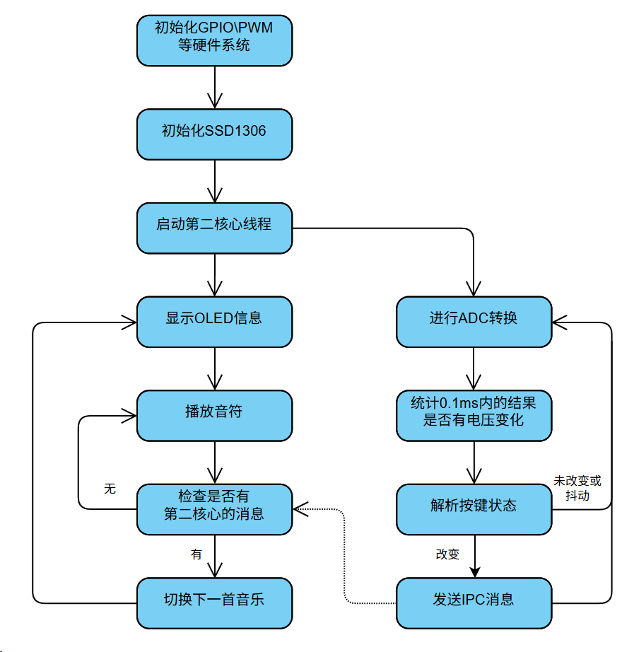
程序结构及框图:
七、测试运行
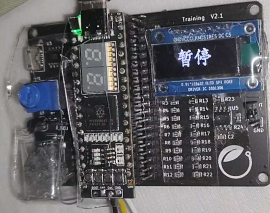
上电初始化完成后,进入暂停状态,等待按键开始播放音乐。
按键切换第一首(小星星),蜂鸣器播放音频,OLED屏幕显示歌曲名称。
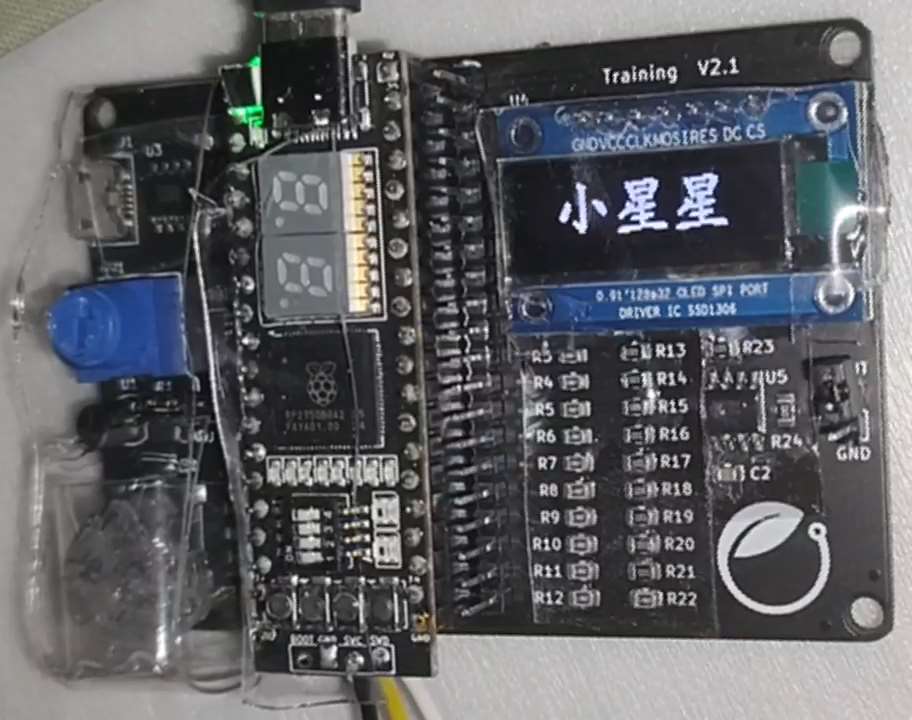
再次按下切换第二首(致爱丽丝),屏幕同步更新。
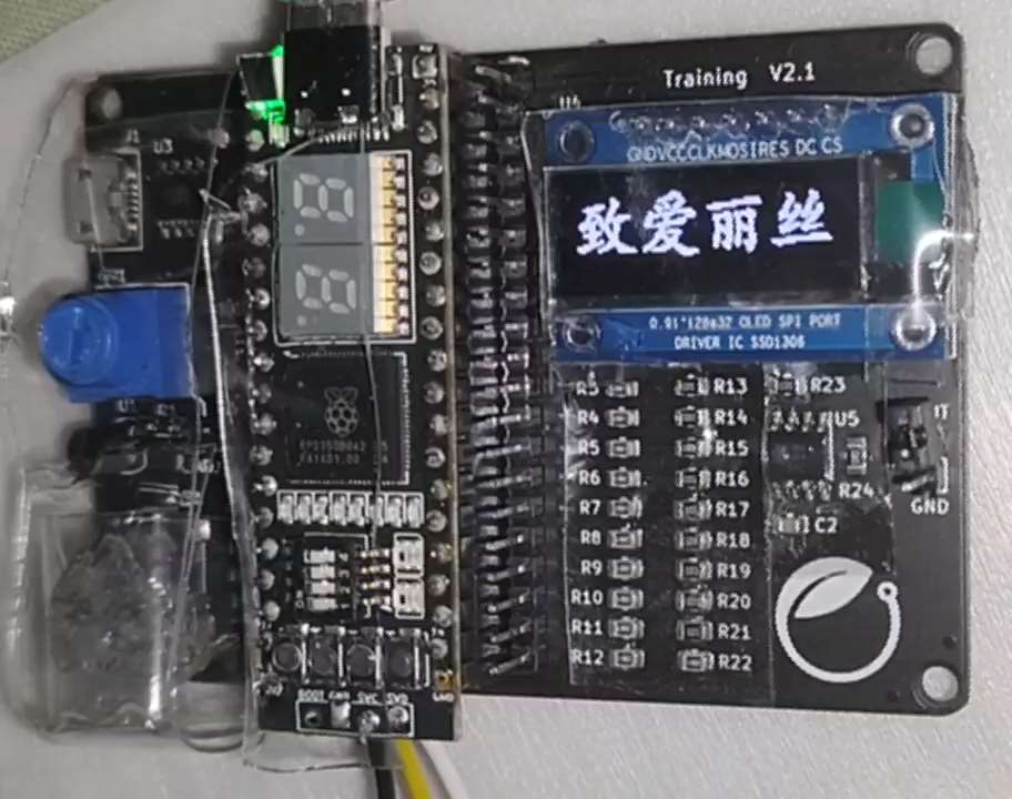
其余功能(例如消抖和音频)图片无法展示,请参见演示视频
八、总结与展望
本次项目探索了实验平台的开发与调试流程,熟悉了OLED模块的操作,练习了多核心开发和跨核心同步。未来可以依托RP2350B平台的扩展性进行更多实验。


 Wang Chong