内容介绍
内容介绍
一、开发板简介
之前接触的都是单核通用 MCU,这次丛得捷购(digikey)拿到一款车规级三核 MCU 开发板 KIT\_AURIX\_TC275\_LITE,其内核 TC275TP 作为第一代 Aurix TC27xT 系列产品,专为满足极高的安全标准同时大幅提高性能而设计。采用创新多核心架构,三个独立的 32 位 TriCore CPU 均可工作在 200 MHz。
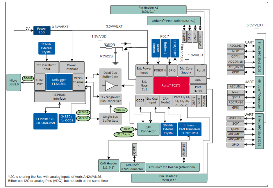
开发板外设及接口功能非常丰富,除了搭载了基于 AURIX™ TriCore™ 单片三核微控制器 TC275 外,还板载 Micro USB 接口的 miniWiggler 调试器、两个 Infineon Shield2Go 扩展接口,还兼容 MikroBUS 和 Arduino 扩展连接,带有 Infineon 新一代 CAN 收发器 TLE9251VSJ ,可用于汽车和工业应用的 HS CAN 网络开发,以及已焊接可调旋转电位计,用于评估模拟电压的采集,当然少不了用户输入按键和 LED 指示灯。
开发板的样子及结构原理框图如下:

二、测试项目简介
简单的点灯测试显然不能体现多核特点,这次就尝试一下三核点灯加休眠测试,即用 TC275 的三个核心,轮流休眠待机,分别控制板卡上的 LED 灯,具体项目任务如下:
cpu0 检测按键按下,唤醒 cpu1(cpu1 翻转 LED1,随即进入 idle 模式); 1 秒后,唤醒 cpu2(cpu2 翻转 LED2,随即进入 idle 模式)。
这里需要说明的是,根据用户手册,TC275 的电源管理控制器(PMC)将整个 MCU 系统区分 Run、Sleep 和 Standby 三种供电模式,而每个 CPU 有 Run、Idle 两种电源模式,Idle 模式是特定于每个 CPU 的,而 Sleep 和 Standby 模式会影响整个系统(包括片内外设),相比来说 Idle、Sleep 和 Standby 模式都是低功耗模式,不过功耗是依次降低的。Standby 模式关闭外设后可能无法响应按键中断(如果我的理解正确,待机模式中除了备份 RAM 和唤醒单元的备份区保持激活供电外,芯片其余部分的电源完全关闭),尽管 Sleep 模式功耗比 Idle 模式更低,但对于每一个 CPU 内核来说,Sleep 模式下 CPU 同样是进入 Idle 状态,因此为了简化测试,将单个 CPU 的 Idle 模式同样认为是休眠状态。至于系统 Sleep 模式下的休眠唤醒方法还有很多,测试还需进一步研究。
三、功能实现
(一)使用的硬件外设资源:Aurix™ Lite Kit 板载外设
Aurix™TC275 Lite-Kit 提供一个用户按钮,一个重置按钮,两个 LED 和一个电位器。此外,LED3 可以用于观测 ESR0 的紧急停止功能(紧急服务请求)。在 ADBUS7 和 ADBUS4 跟踪调试器中,可以使用 LED D1 和 D2 来观察其动作。这次测试只使用了两个 LED 灯和一个用户按钮,在电路中如下所示:
(二)程序实现
开发板可选择多种开发环境,包括 Hightec/PLS/Infineon 的基于 Eclipse 的 FreeEntryToolchain,或来自英飞凌基于 Eslipse 的免费 IDE AURIX™ Development Studio 等等。此次程序开发就使用的是英飞凌自家的 ADS。
AURIX TMDevelopment Studio 是一个综合环境,包括 c -编译器和多核调试器,英飞凌的底层驱动程序(iLLD_infineon's low-level driver),没有时间和代码大小限制的编辑、编译和调试应用程序代码。ADS 界面如下图:
更难能可贵的是,英飞凌官方为开发板提供了丰富的例程,为我们上手测试提供了很大帮助,程序的实现基本就是参考官方例程完成的。
程序主要由 4 部分组成,除了三个内核分别对应了一个主函数外(mainX.c),将主要的功能函数封装在一个 C 文件中,其主要代码片段及说明如下:
/**********************************************************************************************************************
 * \file Cpu0_Main.c
  *********************************************************************************************************************/
#include "My_Multicore_LED.h"
#include "Ifx_Types.h"
#include "IfxCpu.h"
#include "IfxScuWdt.h"

IfxCpu_syncEvent g_cpuSyncEvent = 0;

int core0_main(void)
{
    IfxCpu_enableInterrupts();

    /* !!WATCHDOG0 AND SAFETY WATCHDOG ARE DISABLED HERE!!
     * Enable the watchdogs and service them periodically if it is required
     */
    IfxScuWdt_disableCpuWatchdog(IfxScuWdt_getCpuWatchdogPassword());
    IfxScuWdt_disableSafetyWatchdog(IfxScuWdt_getSafetyWatchdogPassword());

    /* Wait for CPU sync event */
    IfxCpu_emitEvent(&g_cpuSyncEvent);
    IfxCpu_waitEvent(&g_cpuSyncEvent, 1);

    /* Initialize the LEDs and Button before the CPUs synchronization */
    init_GPIOs();
    /* Set the CPUs idle mode      */
    IfxCpu_setCoreMode(&MODULE_CPU1,IfxCpu_CoreMode_idle);
    IfxCpu_setCoreMode(&MODULE_CPU2,IfxCpu_CoreMode_idle);

    while(1)
    {
        control_CoreMode();
    }
    return (1);
}
/**********************************************************************************************************************
 * \file Cpu1_Main.c
 *********************************************************************************************************************/
#include "My_Multicore_LED.h"
#include "Ifx_Types.h"
#include "IfxCpu.h"
#include "IfxScuWdt.h"

extern IfxCpu_syncEvent g_cpuSyncEvent;

int core1_main(void)
{
    IfxCpu_enableInterrupts();

    /* !!WATCHDOG1 IS DISABLED HERE!!
     * Enable the watchdog and service it periodically if it is required
     */
    IfxScuWdt_disableCpuWatchdog(IfxScuWdt_getCpuWatchdogPassword());

    /* Wait for CPU sync event */
    IfxCpu_emitEvent(&g_cpuSyncEvent);
    IfxCpu_waitEvent(&g_cpuSyncEvent, 1);

    while(1)
    {
        toggle_LED1();
        IfxCpu_setCoreMode(&MODULE_CPU1,IfxCpu_CoreMode_idle);
    }
    return (1);
}
/**********************************************************************************************************************
 * \file Cpu2_Main.c
 *********************************************************************************************************************/
#include "My_Multicore_LED.h"
#include "Ifx_Types.h"
#include "IfxCpu.h"
#include "IfxScuWdt.h"

extern IfxCpu_syncEvent g_cpuSyncEvent;

int core2_main(void)
{
    IfxCpu_enableInterrupts();

    /* !!WATCHDOG2 IS DISABLED HERE!!
     * Enable the watchdog and service it periodically if it is required
     */
    IfxScuWdt_disableCpuWatchdog(IfxScuWdt_getCpuWatchdogPassword());

    /* Wait for CPU sync event */
    IfxCpu_emitEvent(&g_cpuSyncEvent);
    IfxCpu_waitEvent(&g_cpuSyncEvent, 1);

    while(1)
    {
        toggle_LED2();
        IfxCpu_setCoreMode(&MODULE_CPU2,IfxCpu_CoreMode_idle);
    }
    return (1);
}
/**********************************************************************************************************************
 * \file My_Multicore_LED.c
  *********************************************************************************************************************/
/*********************************************************************************************************************/
/*-----------------------------------------------------Includes------------------------------------------------------*/
/*********************************************************************************************************************/
#include "IfxPort.h"
#include "IfxScuWdt.h"
#include "SysSe\Bsp\Bsp.h"

/*********************************************************************************************************************/
/*-----------------------------------------------------Macros--------------------------------------------------------*/
/*********************************************************************************************************************/
#define LED1     &MODULE_P00,5   /* Port pin for the LED1     */
#define LED2     &MODULE_P00,6   /* Port pin for the LED2     */
#define BUTTON   &MODULE_P00,7   /* Port pin for the button  */

#define WAIT_TIME   1000            /* Number of milliseconds to wait                */

/*********************************************************************************************************************/
/*-------------------------------------------------Global variables--------------------------------------------------*/
/*********************************************************************************************************************/

/*********************************************************************************************************************/
/*---------------------------------------------Function Implementations----------------------------------------------*/
/*********************************************************************************************************************/
/* Function to configure the port pins for the push button and the LEDs */
void init_GPIOs(void)
{
    /* Setup the port pin connected to the LED to general output mode push-pull. This function can be used
     * to initialize any port pin by specifying the port number, pin number and port pin mode.
     */
    IfxPort_setPinMode(LED1, IfxPort_Mode_outputPushPullGeneral);
    IfxPort_setPinMode(LED2, IfxPort_Mode_outputPushPullGeneral);
    /* Setup the port pin connected to the push button to input mode. This function can be used to initialize any
     * port to input mode by just specifying the port number as illustrated.
     */
    IfxPort_setPinMode(BUTTON, IfxPort_Mode_inputPullUp);

}

/* Depending on the the state of the "BUTTON" port pin, the BUTTON wake cpu1 and cpu2 in turn */
void control_CoreMode(void)
{
    /* With the routine getPinState() the value of a particular pin can be retrieved. This
     * function can be used to retrieve any port state by just specifying the port number
     * as illustrated.
     */
    if(IfxPort_getPinState(BUTTON) == 0)
    {
        IfxCpu_setCoreMode(&MODULE_CPU1,IfxCpu_CoreMode_run);
        waitTime(IfxStm_getTicksFromMilliseconds(BSP_DEFAULT_TIMER, WAIT_TIME));    /* Wait 1000 milliseconds            */
        IfxCpu_setCoreMode(&MODULE_CPU2,IfxCpu_CoreMode_run);

    }
//    else
//    {
//        IfxCpu_setCoreMode(&MODULE_CPU1,IfxCpu_CoreMode_idle);
//        IfxCpu_setCoreMode(&MODULE_CPU2,IfxCpu_CoreMode_idle);
//    }
}

/* This function toggles the port pin and wait */
void toggle_LED1(void)
{
//    waitTime(IfxStm_getTicksFromMilliseconds(BSP_DEFAULT_TIMER, WAIT_TIME));    /* Wait 100 milliseconds            */
    IfxPort_togglePin(LED1);                                                     /* Toggle the state of the LED1      */
}

/* This function toggles the port pin and wait */
void toggle_LED2(void)
{
    IfxPort_togglePin(LED2);                                                     /* Toggle the state of the LED2      */
//    waitTime(IfxStm_getTicksFromMilliseconds(BSP_DEFAULT_TIMER, WAIT_TIME/10));    /* Wait 100 milliseconds            */
}
四、心得体会
主要有三个方面的心得体会,一是不一样,二不一般,三是有遗憾。
说不一样,主要是作为一个以51单片机入门和ARM系列应用为主的初学者来说,这款TC275开发板是全新的体验,虽然只是对TriCore内核进行了初步理解,但通过对比学习对微处理器知识架构有了新的理解和完善。
所谓不一般,这是一款车规级MCU,英飞凌是汽车和工业应用著名器件供应商,早已耳闻但从未使用过它的MCU。这款KIT_AURIX_TC275_LITE开发板,其功能确实非常强大,支持更多的汽车电子总线应用接口,还有MikroBUS 和Arduino扩展连接,这些接口集成在一块开发板上的少有。另外TC275是一个多核的处理器,英飞凌官方为开发板提供了丰富的例程,使用英飞凌底层驱动库(iLLD)开发这也是首次体验。
第三个是有遗憾,因为对于这一次的活动来说,它只需要做一个简单的点灯等基本的功能就可以完成,甚至我没有把配的插针焊上去就完成了此次活动任务。有点小遗憾没有能够充分的去学习研究它强大的功能作用。单独点有点一个灯感觉还是有点浪费了。另外在我的项目中,完成的休眠方式并不是最优方案,仅仅完成了内核休眠,更有意义的节能,应当是系统 Sleep 模式下的休眠。
所以说可以学习的东西还很多,这块开发板的价值还有待挖掘,比如MikroBUS 和Arduino扩展连接,还可以接WiFi和蓝牙,OneEye界面设计也很方便,有必要后期好好把这个板子玩玩。
附件下载

My_Multicore_LED.rar
项目代码
“Funpack2-2”-英飞凌车规级三核MCU开发板KIT_AURIX_TC275_LITE上手测试(多核休眠互调).zip
项目说明文件MD
团队介绍
都市木头
评论
0 / 100
查看更多
