众筹网站发布的产品 —图像/视频
收藏
分享
脑图
Crowdsupply众筹网站上发布的产品 - 图像/视频

网站介绍
Crowsupply是位于美国俄勒冈州Portlan市的一家专注于电子创意产品的众筹网站
相关项目
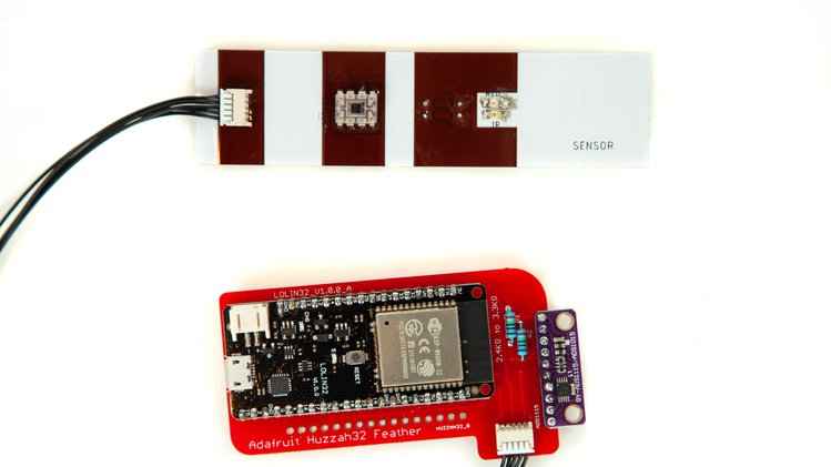
概述:脑血流生物反馈符合经济实惠的物联网技术
关键特性

概述:开源生物医学成像
关键特性
众筹价格:349美元
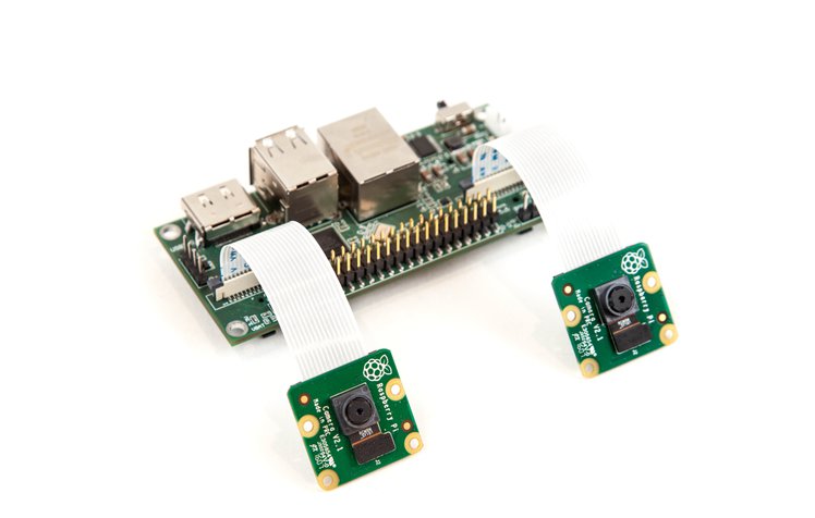
概述:基于Raspberry Pi的开源立体相机
关键特性
众筹价格:89美元
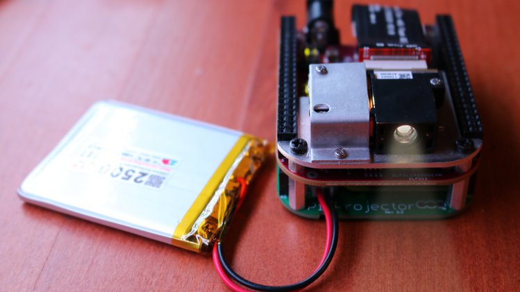
概述:Raspberry Pi动力袖珍投影仪
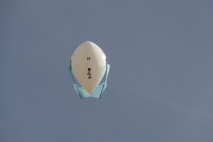
概述:风筝气球为摄像,通讯和气象提供安静,长期的飞行。
关键特性
众筹价格:5美元
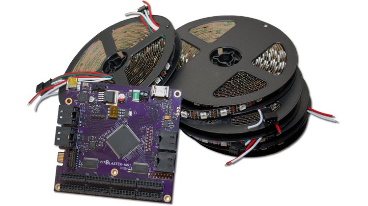
概述:结合LED灯条创建一个巨大的显示器,充当常规视频监视器。
关键特性
概述:采用PCI Express外形的开放式视频开发板,支持在加密视频信号上叠加内容。 让我们为数字时代带来开放的视频!
关键特性
众筹价格:215美元
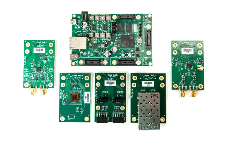
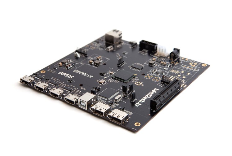
概述:开放式模块化ARM + FPGA开发平台,采用新的SYZYGY标准,适用于高性能外设
结构框图
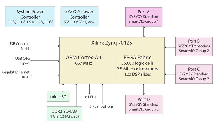
关键特性
众筹价格:350美元
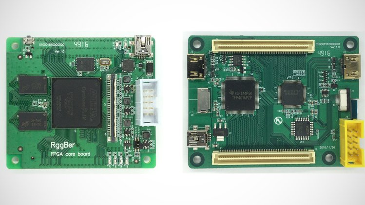
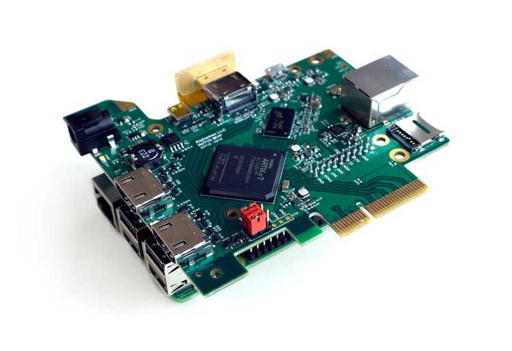
概述:一种开源,模块化,基于FPGA的开发套件,使嵌入式视觉设计变得简单且经济实惠。
关键特性
众筹价格:49美元
概述:用于记录,路由和操作HDMI和DisplayPort视频信号的开放式平台。
关键特性
概述:关于波特兰创客运动的权威着作。
众筹价格:35美元
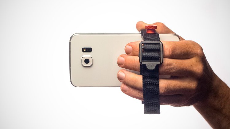
概述:GRIPT是一款适用于智能手机的三脚架适配器和手柄。
详细介绍

概述:陆军第25步兵师Charlie Haughey在越南拍摄的一本珍贵照片。
众筹价格:55美元
评论
0 / 100
查看更多
 每日资讯
每日资讯2019-08-02
1777

Copyright © 2024 苏州硬禾信息科技有限公司 All Rights Reserved 苏ICP备19040198号