选用示波器要考虑的12个要素
收藏
分享
脑图
选用示波器要考虑的12个要素
文章背景:
标题:12 THINGS TO CONSIDER WHEN CHOOSING AN OSCILLOSCOPE
关于数字示波器
Oscilloscopes are the basic tool for anyone designing, manufacturing or repairing electronic equipment. A digital storage oscilloscope (DSO, which this guide concentrates on) acquires and stores waveforms. It can show high-speed repetitive and single-shot signals across multiple channels to capture elusive glitches and transient events.
A scope shows the signal’s frequency, whether a malfunctioning component is distorting the signal, how much of the signal is noise, whether the noise changes with time, and much, much more.
In short, whatever scope you choose it must not only match how and where you work but also:
Accurately capture your signals.
you will need a pretty good idea of what signals you’re going to need to look at: whether (analog) audio and transducer signals or (digital) pulses and steps. If you’re looking at digital signals, will you be measuring rise times, or just looking at approximate timing relationships? Will you use the scope to qualify elements of your design, or mostly for debugging? Either way, accurate signal capture at the outset is more important than any later signal processing – your decisions rely on accurate information, and you can always process the information on a computer.
Have features that expand your capabilities and save you time.
you need to consider not just your present generation of designs, but future generations too. A high-quality scope will give you many years’ reliable service.
Offer guaranteed not just typical specifications.
Ensure that all the parameters you need to measure are detailed as “guaranteed specifications” in the oscilloscope datasheet. Parameters listed as “Typical” are simply an indication of oscilloscope performance, and cannot be used to make meaningful measurements that comply with recognised quality standards
要素1: 带宽
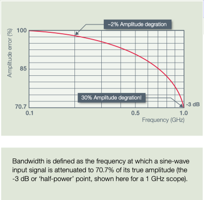
System bandwidth determines an oscilloscope’s fundamental ability to measure an analog signal - the maximum frequency range that it can accurately measure.
What you need
Entry level scopes will often have a maximum bandwidth of 100 MHz. They can accurately (within 2%) show the amplitudes of sine-wave signals up to 20 MHz.
For digital signals, oscilloscopes must capture the fundamental, third and fifthharmonics or the display will lose key features. So, the bandwidth of the scope together with the probe should similarly be at least 5x the maximum signal bandwidth for better than ±2% measurement error – the ‘five times rule’. This is also needed for accurate amplitude measurements
High-speed digital, serial communications, video and other complex signals can therefore require scope bandwidths of 500 MHz or more.
Remember the ‘five times rule’
When selecting bandwidth, use the ‘five times rule’. If bandwidth is too low, your oscilloscope will not resolve high-frequency changes. Amplitude will be distorted. Edges will vanish. Details will be lost.
要素2: 上升时间
While analog engineers look at bandwidth, digital engineers are more interested in the rise time of signals like pulses and steps.
What you need
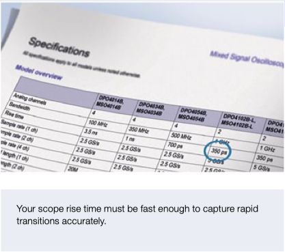
The faster the rise time, the more accurate are the critical details of fast transitions. Fast rise time is also needed for accurate time measurements.
Rise time is defined as, where k is between 0.35 (typically for scopes with bandwidth <1 GHz) and 0.40 to 0.45 (>1 GHz).
Similar to bandwidth, an oscilloscope’s rise time should be < 1/5 x fastest rise time of signal. E.g. a 4-ns rise time needs a scope with faster than 800 ps rise time. Note: As with bandwidth, achieving this rule of thumb may not always be possible.
TTL and CMOS may need 400 to 300 ps rise times.
Accurate rise time measurements are key
Many logic families have faster rise times (edge speeds) than their clock rates suggest. A processor with a 20 MHz clock may well have signals with rise times similar to those of an 800 MHz processor. Rise times are critical for studying square waves and pulses. Square waves are standard for testing amplifier distortion and timing signals for T vs and computers. Pulses may represent glitches or information bits – too slow a rise time for the circuit being tested could shift the pulse in time and give a wrong value.
要素3: 探头的匹配
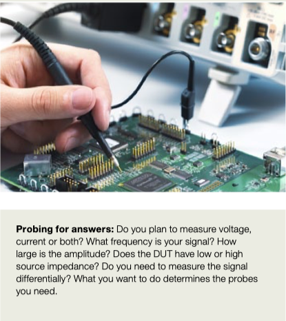
Precision measurements start at the probe tip. The probe’s bandwidth must match that of the oscilloscope (the ‘five times rule’ again), and must not overload the Device Under Test (DUT).
What you need
Probes actually become a critical part of the circuit, introducing resistive, capacitive and inductive loading that alters the measurement. To minimize the effect it’s best to use probes from the same manufacturer as the scope, forming an integrated solution.
Loading is critical. Resistive loading of standard passive probes is usually an acceptable 10 MΩ or better. Capacitive loading of 10, 12 or even 15 picoFarads (pF) at high frequencies is a real problem though.
When selecting a mid-range scope choose probes with capacitive loadings of < 10 pF. The best passive probes offer 1GHz bandwidth with a capacitive load <4 pF.
Use a range of probes
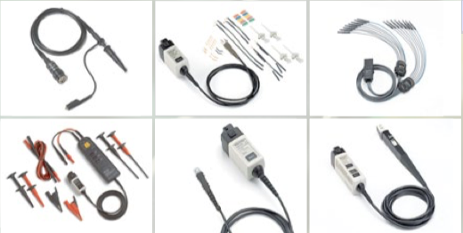
To start with, select passive probes that have high bandwidth and low loading. Active ground-referenced probes offer 1 to 4 GHz bandwidth, and differential active probes 20 GHz or more. Adding a current Probe enables the scope to calculate and display instantaneous power, true power, apparent power, and phase. High voltage probes measure to 40 kv peak. Specialty probes include logic, optical and environmental types.
要素4: 通道的准确并且足够
Digital scopes sample analog channels to store and display them. In general, the more channels the better, although adding channels adds to the price.
What you need
Whether to select 2, 4, 8 or 16 channels depends on your application. Two or four analog channels will allow you to view and compare signal timings of your waveforms, while debugging a digital system with parallel data needs an additional 8 or 16 digital channels or more.
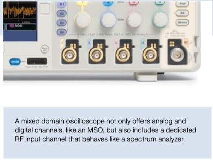
A Mixed Signal Oscilloscope adds digital timing channels, which indicate high or low states and can be displayed together as a bus waveform. The latest Mixed Domain Oscilloscopes add a dedicated RF input for making high frequency measurements in the frequency domain.
Whatever you choose, all channels should have good range, linearity, gain accuracy, flatness and resistance to static discharge.
Some instruments share the sampling system between channels to save money. But beware: the number of channels you turn on can reduce the sample rate.
Isolated channels simplify floating measurements. Unlike ground-referenced oscilloscopes, the input connector shells can be isolated from each other and from earth ground.
Choose enough channels
The more time-correlated analog and digital channels your scope has, the more points in a circuit you can measure at the same time and the easier it is to decode a wide parallel bus, for instance. The example shows 2 analog, 8 digital and 1 decoded bus waveforms.
要素5:快速的取样率
The sample rate of an oscilloscope is similar to the frame rate of a movie camera. It determines how much waveform detail the scope can capture.
What you need
Sample rate (samples per second, S/s) is how often an oscilloscope samples the signal. Again, we recommend a ‘five times rule’: use a sample rate of at least 5x your circuit’s highest frequency component.
The minimum sample rate may also be important if you need to look at slowly changing signals over longer periods of time.
Most entry-level scopes have a (maximum) sample rate of 1 to 2 GS/s, while mid-range ones can have 5 to 10 GS/s.
The faster you sample, the less information you’ll lose and the better the scope will represent the signal under test. But the faster you will fill up your memory, too, which limits the time you can capture.
To capture glitches you need speed!
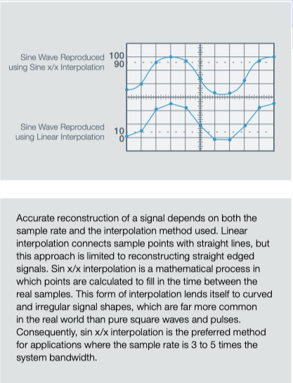
Nyquist said that a signal must be sampled at least twice as fast as its highest frequency component to accurately reconstruct it and avoid aliasing (showing artefacts that are not actually there). Nyquist however is an absolute minimum – it applies only to sine waves, and assumes a continuous signal. Glitches are by definition not continuous, and sampling at only twice the rate of the highest frequency component is usually not enough. Conclusion: A high sample rate increases resolution, ensuring that you’ll see intermittent events.
要素6:多种触发模式
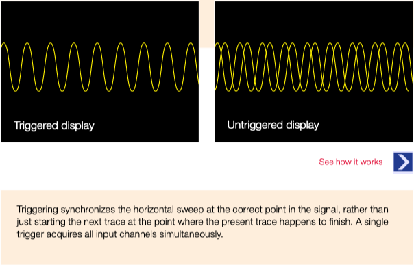
Triggering gives a stable display and lets you zero in on specific parts of complex waveforms
What you need
All oscilloscopes provide edge triggering, and most offer pulse width triggering.
To acquire anomalies and make best use of the scope’s record length, look for a scope that offers advanced triggering on more challenging signals.
The wider the range of trigger options available the more versatile the scope (and the faster you get to the root cause of a problem!):
A & B sequence triggering; delay by time or delay by events
video triggering on line/frame/HD signals, etc.
Logic triggering: slew rate, glitch, pulse width, time-out, runt, setup-and-hold
Communications triggers: embedded system designs use both serial (I 2 C, SPI,CAN/LIN, USB …) and parallel buses.
Advanced triggers find the right information
Triggering lets you isolate a group of waveforms to see what is going wrong. Specialized triggers can respond to specific conditions in the incoming signal making it easy to detect, for example, a pulse that is narrower than it should be.
要素7: 足够的记录长度
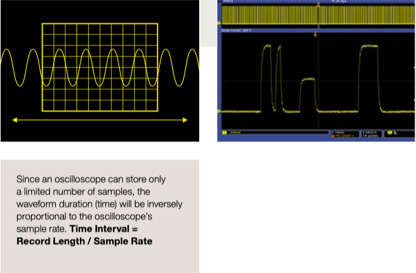
Record length is the number of points in a complete waveform record. A scope can store only a limited number of samples so, in general, the greater the record length the better.
What you need
Time captured = record length/sample rate. So, with a record length of 1 Mpoints and a sample rate of 250 MS/sec, the oscilloscope will capture a signal 4 ms in length.
Today’s scopes allow you to select the record length to optimize the level of detail needed for your application.
A good basic scope will store over 2,000 points, which is more than enough for a stable sine-wave signal (needing perhaps 500 points). But to find the causes of timing anomalies in a complex digital data stream you should consider, for example, a DPO (Digital Phosphor Oscilloscope) with a record length of 1 Mpoints or more.
To search for infrequent transients such as jitter, runt pulses and glitches, select at least a mid-end scope that combines long record length with a high waveform capture rate.
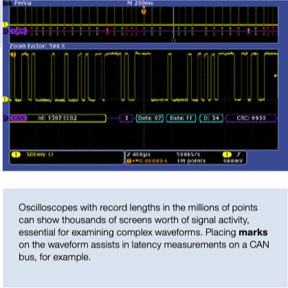
See the bigger picture
Capturing enough detail to decode this USB serial data stream requires high resolution sampling (200ps). Capturing multiple packet contents needs a long time (200µs). An oscilloscope with long record length (1 Mpoints) is needed to display both.
要素8: 强大的波形浏览和分析功能
Searching for specific waveform errors can be like searching for a needle in a haystack. you need tools that automate the process and accelerate the “time to answer”.
What you need
Zoom & Pan allows you to zoom in on an event of interest, and pan the area backwards and forwards in time.
Play & Pause automatically pans the zoom window across the waveform. That allows hands-free playback so you can concentrate on what’s important – the waveform itself.
Marks lets you mark events of interest while you’re looking for a problem. you can use front-panel controls to rapidly jump between each mark for quick and easy timing measurements (see panel).
Search & Mark lets you search through the entire acquisition and automatically mark every occurrence of a user-specified event.
Advanced search lets you define various different criteria, similar to trigger conditions, which will be automatically detected and marked in the captured waveform.
Consider advanced search tools
The industry’s fastest tool for automated navigation, search and analysis is Wave Inspector ® , a proprietary technology. It allows you to specify search criteria to automatically find every occurrence in an acquisition that violates some specified criteria such as setup and hold time
要素9: 自动化的波形参数测量
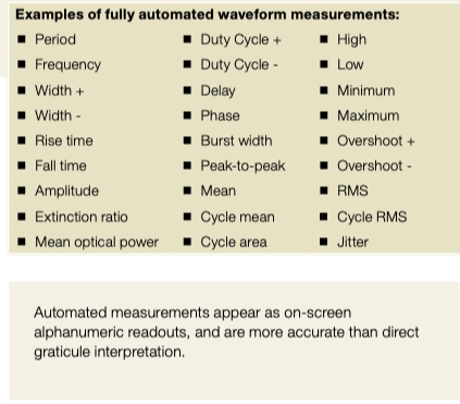
Automated waveform measurements make it easier to obtain accurate numerical readings.
What you need
Most scopes offer front-panel buttons and/or screen-based menus to take accurate automated measurements.
Basic choices on most scopes include amplitude, period and rise/fall time.
Many digital scopes also provide mean and RMS calculations, duty cycle, and other maths operations.
Advanced mathematics functions are found on some scopes, improving the ‘time to answer’ even further. Some examples:
FFT, Integrate, Differentiate, Logarithm, Exponent, Square root, Absolute
Sine, Cosine, Tangent, Radians, Degrees
Scalars, with user-adjustable variables and results of parametric measurements.
Look for fast answers
Once again, extra functions shorten the time to answer. Digital Signal Processing techniques can automate measurements – making them faster, more accurate and more repeatable than is possible with cursors. you can even write your own formulae for specific maths functions.
要素10: 先进的应用支持
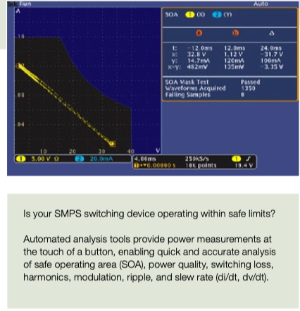
Advanced scopes have application software for optical and electrical design troubleshooting and standards compliance.
What you need
Signal integrity and jitter measurement packages: provide insight into signal integrity-related problems in digital systems, their causes, characteristics and effects.
RF applications: view signals in the frequency domain and analyze using spectrograms, amplitude, frequency and phase versus time traces.
Support for debug of embedded systems with mixed analog & digital, parallel & serial technologies such as CAN/LIN, I 2 C, SPI, FlexRay, MOST and others.
Education: electrical engineering students need to understand complex circuits and electronic designs to develop next generation technologies.
Power measurement (SMPS, for example): automated measurements for power quality, switching loss, harmonics, safe operating area, modulation, ripple, slew rate and more.
Others include optical communications, memory system verification, communications standards testing, disk drive measurements, video measurements, and more.
Think about your future needs
Complex electronic designs are driving innovation across many industries today. your scope should have all the features your application needs – now and in the future.
要素11: 简单、快速响应的操作
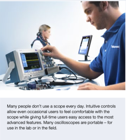
Oscilloscopes should be easy to operate, even for occasional users. The user interface is a large part of the ‘time to answer’ calculations.
What you need
Frequently used adjustments should have dedicated knobs.
AUTOSET and/or DEFAULT buttons will make for instant setup.
The scope should be responsive, reacting quickly to changing events
There should be support for your own language, with templates for the dials.
Controls that match your way of working
Oscilloscopes should give you different ways to operate the instrument. Built-in help can provide a convenient, built-in reference manual, while smart menus give easy access to multifunction, context-sensitive commands.
要素12: 连接和扩展
Connecting a scope to a computer directly or transferring data via portable media allows advanced analysis, and simplifies documenting and sharing results.
What you need
Consider a scope that allows you to access a Windows desktop and provide network printing and file sharing resources.
Check if it can run third-party analysis, documentation and productivity software.
Is it helpful to provide internet access, and share measurements with colleagues real-time?
Can it meet your needs as they change? For example, can you add:
Memory to channels to analyze longer record lengths
Application-specific measurements and application modules
A full range of probes and modules
Accessories like battery packs and rack mounts
Software to control the scope from your PC, take automated measurements, waveform data logging and export waveforms live.
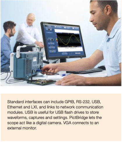
Ask about interfaces
LAN, Display, and Printer interfaces enable you to integrate your oscilloscope with the rest of your working environment:
Ethernet port for network connectivity, plus compatible software to capture screen-shots, waveform data and measurement results
USB Host port: quick & easy data storage, printing, and connecting a USB keyboard
USB device port for easy connection to a PC or direct printing to a printer
video port to export the oscilloscope display to a monitor or projector
评论
0 / 100
查看更多
 硬禾发布
硬禾发布2019-10-04
1470

Copyright © 2024 苏州硬禾信息科技有限公司 All Rights Reserved 苏ICP备19040198号